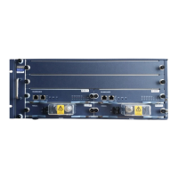
There are a number of buttons on the panel, such as RST, EXCH and CPY. Their
functions are as shown in Table 4-2.
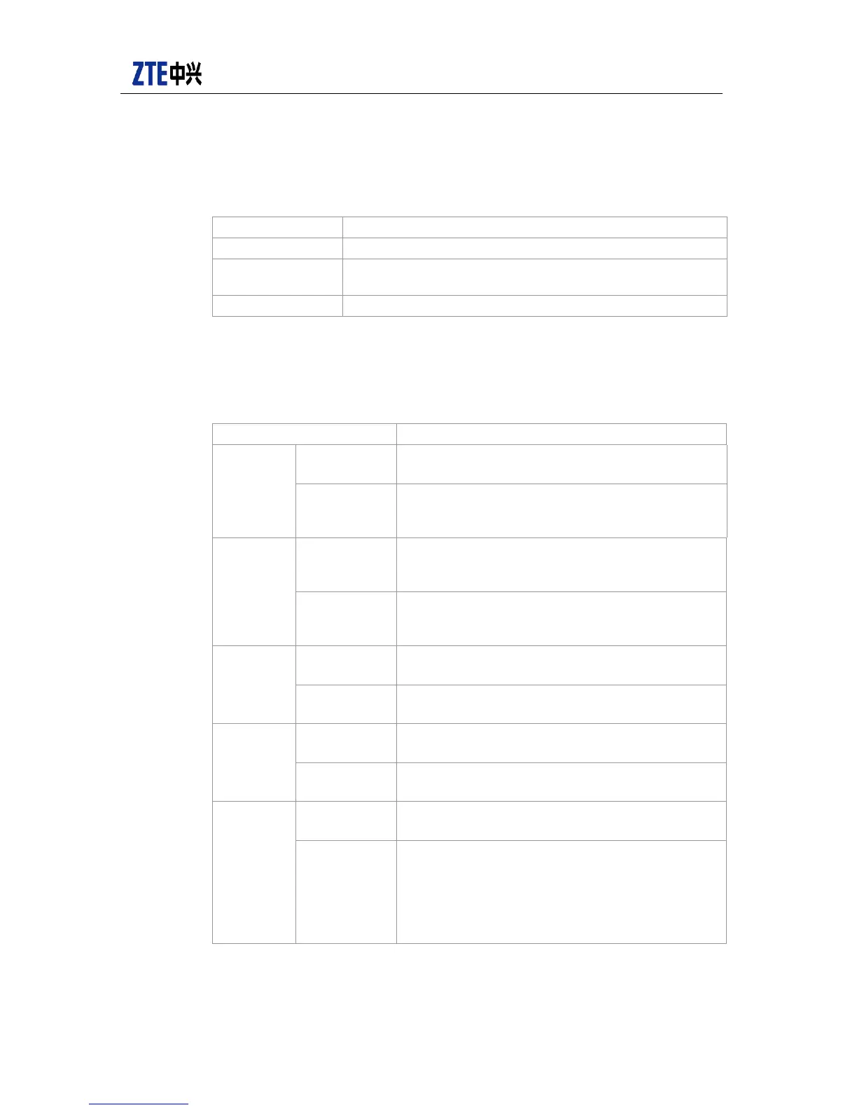
Table 4-2 Main control board panel button function description
Button name Function
RST Board reset button, used to reset the whole board
EXCH
Board switching button, used to switch the active main control
board to standby board
CPY Reserved, not used
The functions of the indicators on the main control board panel are as shown in Table
4-3.
Table 4-3 Main control board panel indicator function description
Indicator Function
1~2/5/8/12
RUN (green)
Off: corresponding line card fault or not in position
Flash: corresponding line card works properly
ALM (red)
Off: corresponding line card has no alarm or not in
position
On: corresponding line card has alarm
PWR1~2/3
RUN (green)
Off: corresponding power module fault or not in
position
On: corresponding power module works properly
ALM (red)
Off: corresponding power module has no alarm or not
in position
On: corresponding power module has alarm
RUN
RUN (green)
Off: this main control board has fault
Flash: this main control board works properly
ALM (red)
Off: this main control board has no alarm
On: this main control board has alarm
MST
RUN (green)
On: this board is active
Off: this board is standby
ALM (red)
On: active/standby status is exceptional
Off: active/standby status is normal
FAN (only
8902E has
this
indicator;
for others,
this is
displayed
on the fan
frame)
RUN (green)
On: fan frame power supply is normal
Off: fan frame power supply is exceptional
ALM (red)
On: fan frame works exceptionally
Off: fan frame works properly or power supply is
exceptional
 Loading...