15MD Evolution – Dialog 4425 IP Vision
Your Extension’s Accessories
Inserting the Labels for the Add-on Key
Panels
Each satellite is designed to have a label.
It is designed so you may indicate what functions have been
programmed on the various satellite repertory keys (see the
“Physical Programming of Your Extension” section.)
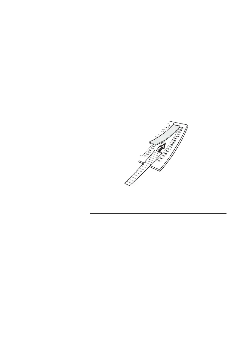
This label is protected by a plastic cover.
To insert or remove the label, lift the protective cover as illustrated
below.
Note: If you need a new label, contact your system
administrator.
Installation and Cables for an Add-on
Interface Module
An add-on interface module would be located on the underside of
your extension, in the rectangular opening on the underside of your
extension, designed for this purpose.
It is connected to your extension with a connector that features a
rigid extender attached with three torx-type screws that require an
adapted screwdriver.
The external ring device or the external visual device directly
connects to the module using an RJ12 connector.
 Loading...