12 266HSH MODBUS TRANSMITTER | PRESSURE/TEMPERATURE MULTIVARIABLE | OI/266HSHMT-EN REV. A
6.6 Electrical connection
6.7 Electrical data for inputs and outputs
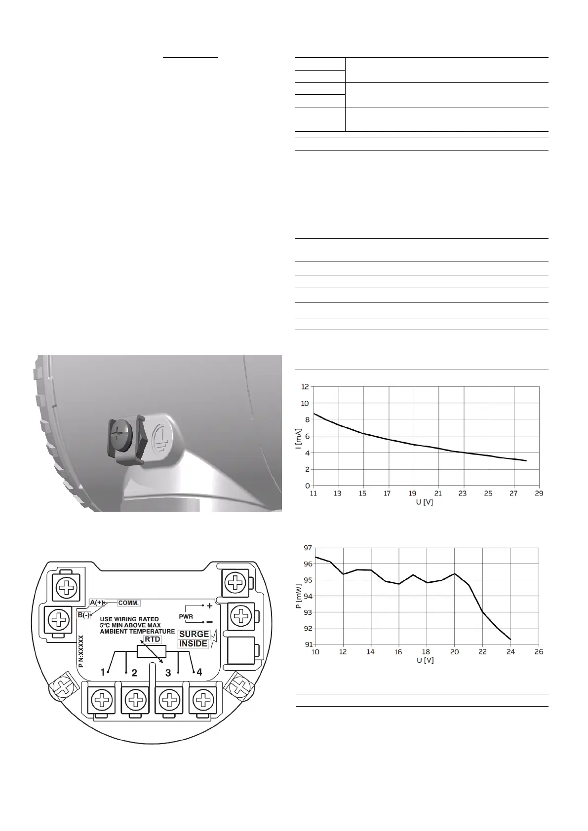
Fig. 10: Terminals
6.5 Grounding
Pressure transmitter housing should be grounded or
earthed in accordance with national and local electrical
codes. Ground connection is mandatory for surge
protector equipped devices in order to ensure proper
functioning.
Protective grounding terminals (PE) are available outside
and/or inside the housing of the transmitter. Both ground
terminals are electrically connected and it up to the user to
decide which one to use. The most effective transmitter
case grounding method is direct connection to earth
ground with impedance equal or less of 5 ohm.
6.1 Surge protector equipped terminal block
(optional)
Terminal
PWR+
PWR-
A (+)
B (-)
1, 2, 3, 4
Function/comment
Power supply
Modbus interface RS485
Terminals for connecting the Pt100
resistance thermometer
Connection of a Pt100 temperature sensor
For the purpose of simulation, a 178 Ω resistor (206 °C /
402.8 °F) with 2 jumpers has been installed between the
terminals for the Pt100 connection.
This resistor (including the jumpers in the case of 4-wire
connections) must be removed before connecting the
Pt100 If a Pt100 is not connected, the resistor must not be
removed.
For current draw requirements see Fig. 25.
For power consumption based on specific supply voltages
see Fig. 26.
i
i
Terminals
Supply Voltage
PWR + / PWR -
10.5 ... 30 V DC
The Modbus protocol is not secure, as such the intended
application should be assessed to ensure that these
protocols are suitable before implementation.
i
Where:
L = Line length in meters
R = Total resistance in Ω (ohms)
C = Line capacitance in pF/m
Cf = Maximum internal capacitance of the HART field
devices located in the circuit, in pF
Avoid routing cables with other electrical cables (with
inductive load, etc.) or near large electrical equipment.
65 x 10
6
R x C
L =
C
f
+ 10000
C
–

 Loading...


