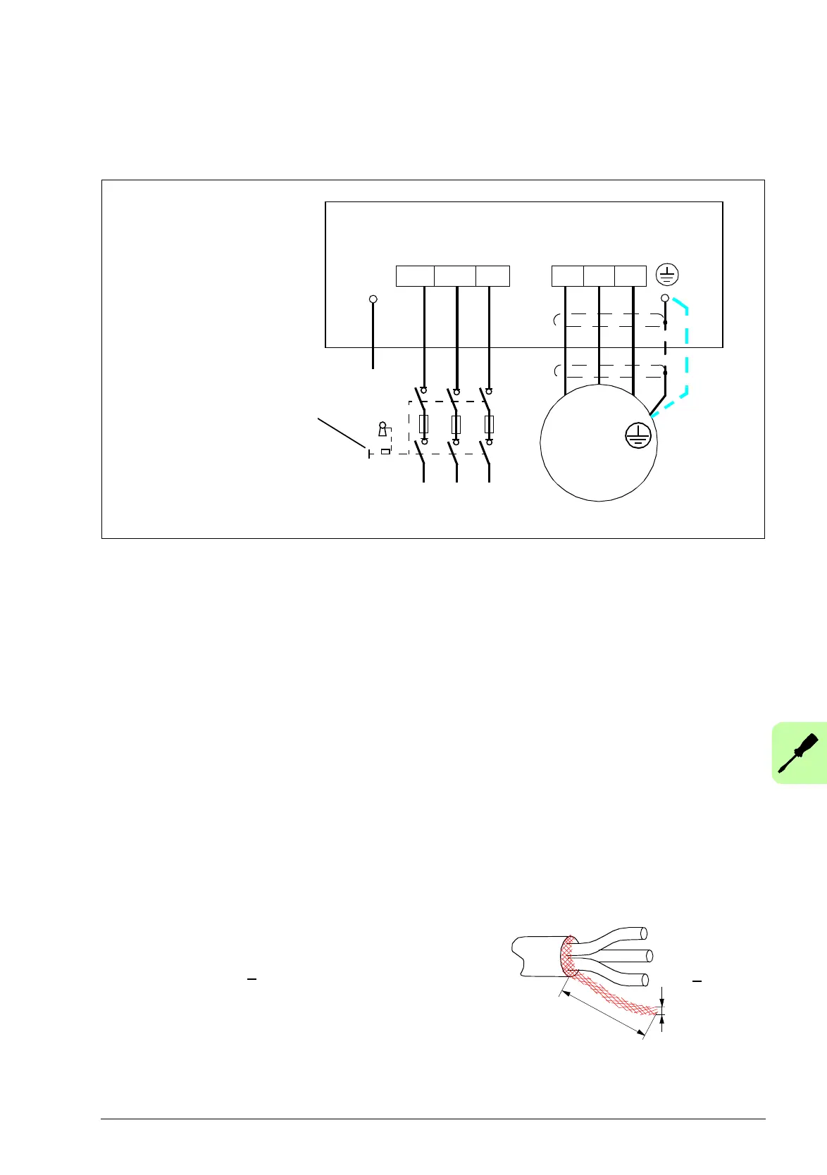
U2 V2 W2
INPUT
1)
Drive
For alternatives, see chapter
Planning the electrical
installation, section Selecting
the supply disconnecting
device (disconnecting
means) in ACS320 user’s
manual (3AUA0000062599
[English]).
OUTPUT
U1/L V1/N W1
Motor
3 ~
V1
U1 W1
PE
PE
L1 L2 L3
1)
Ground the other end of the PE conductor at the distribution board.
2)
Use a separate grounding cable if the conductivity of the cable shield is insufficient (smaller
than the conductivity of the phase conductor) and there is no symmetrically constructed
grounding conductor in the cable. See chapter Planning the electrical installation, section
Selecting the power cables in ACS320 user’s manual (3AUA0000062599 [English]).
3)
L and N are connection markings for the 1-phase power supply.
Note:
• Do not use an asymmetrically constructed motor cable.
• If there is a symmetrically constructed grounding conductor in the motor cable in addition to
the conductive shield, connect the grounding conductor to the grounding terminal at the
drive and motor ends.
• For the 1-phase power supply, connect power to terminals U1/L and V1/N.
• Route the motor cable, input power cable and control cables separately. For more
information, see chapter Planning the electrical installation, section Routing the cables in
ACS320 user’s manual (3AUA0000062599 [English]).
Grounding of the motor cable shield at the motor end
For minimum radio frequency interference:
• ground the cable by twisting the shield as follows:
flattened width >
1/5 · length
• or ground the cable shield 360 degrees at the lead-
through of the motor terminal box.

 Loading...


