Electrical installation 21
Connecting the control cables
Default I/O connection diagram
The default connection of the control signals depends on the application macro in
use, which is selected with parameter 9902 APPLIC MACRO.
The default macro is the HVAC Default macro. It provides a general purpose I/O
configuration with three constant speeds. Parameter values are the default values
given in chapter Actual signals and parameters in ACS320 user’s manual
(3AUA0000062599 [English]).
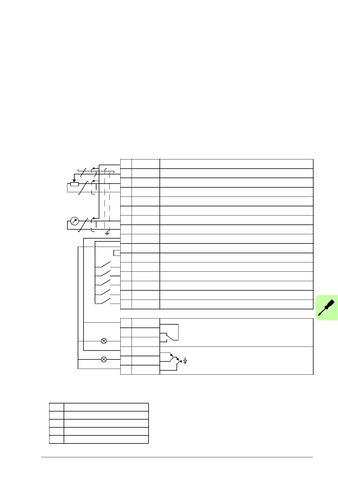
The default I/O connections for the HVAC Default macro are given in the figure below.
X1A
1 SCR Signal cable shield (screen)
2AI1 External reference: 0…10 V or 0...20 mA
3 GND Analog input circuit common
4 +10V Reference voltage: +10 V DC, max. 10 mA
5 AI2 PID feedback 0…10 V or 0...20 mA
6 GND Analog input circuit common
7AO Output frequency value: 0…20 mA
8 GND Analog output circuit common
9 +24V Auxiliary voltage output: +24 V DC, max. 200 mA
10 GND Auxiliary voltage output common
11 DCOM Digital input common
12 DI1 Stop (0) / Start (1)
13 DI2 Not Configured
14 DI3 Constant speed selection
1)
15 DI4 Safety Interlock
16 DI5 Not Configured
X1B
17 ROCOM Relay output 1
Default operation: Ready
18 RONC
19 RONO
20 DOSRC Digital output, max. 100 mA
No fault [Fault (-1)]
21 DOOUT
22 DOGND
max. 500 ohm
1…10 kohm
1)
See parameter group 12 CONSTANT
SPEEDS:
2)
360 degree grounding under a clamp.
Tightening torque: 0.4 N.m (3.5 lbf.in).
DI3 Operation (parameter)
0 Set speed through AI1
1 Speed 1 (1202)
0 Speed 2 (1203)
1 Speed 3 (1204)

 Loading...


