Resistor braking
160
Note: A resistor other than the standard resistor can be used provided that:
• its resistance is not lower than the resistance of the standard resistor.
WARNING! Never use a brake resistor with a resistance below the value specified
for the particular drive / brake chopper / resistor combination. The drive and the
chopper are not able to handle the overcurrent caused by the low resistance.
• the resistance does not restrict the braking capacity needed, that is,
where
• the heat dissipation capacity (E
R
) is sufficient for the application (see step 3
above).
Optional brake chopper and resistor(s) for the ACS800-01/U1
The nominal ratings for dimensioning the brake resistors for the ACS800-01 and
ACS800-U1 are given below at an ambient temperature of 40 °C (104 °F).
P
max
maximum power generated by the motor during braking
U
DC
voltage over the resistor during braking, e.g.,
1.35 · 1.2 · 415 V DC (when supply voltage is 380 to 415 V AC),
1.35 · 1.2 · 500 V DC. (when supply voltage is 440 to 500 V AC) or
1.35 · 1.2 · 690 V DC (when supply voltage is 525 to 690 V AC).
R resistor resistance (ohm)
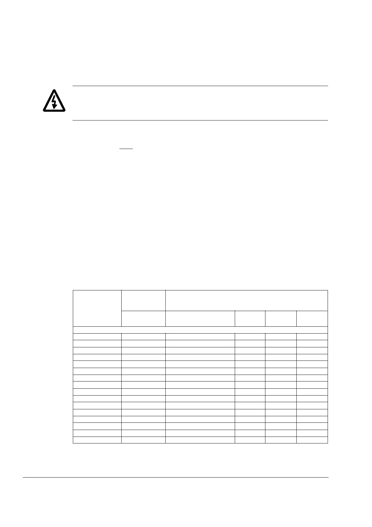
ACS800-01 type
ACS800-U1 type
Braking power
of the chopper
and the drive
Brake resistor(s)
P
brcont
(kW)
Type R
(ohm)
E
R
(kJ)
P
Rcont
(kW)
230 V units
-0001-2 0.55 SACE08RE44 44 210 1
-0002-2 0.8 SACE08RE44 44 210 1
-0003-2 1.1 SACE08RE44 44 210 1
-0004-2 1.5 SACE08RE44 44 210 1
-0005-2 2.2 SACE15RE22 22 420 2
-0006-2 3.0 SACE15RE22 22 420 2
-0009-2 4.0 SACE15RE22 22 420 2
-0011-2 5.5 SACE15RE13 13 435 2
-0016-2 11 SAFUR90F575 8 1800 4.5
-0020-2 17 SAFUR90F575 8 1800 4.5
-0025-2 23 SAFUR80F500 6 2400 6
-0030-2 28 SAFUR125F500 4 3600 9
-0040-2 33 SAFUR125F500 4 3600 9
-0050-2 45 2xSAFUR125F500 2 7200 18
-0060-2 56 2xSAFUR125F500 2 7200 18
-0070-2 68 2xSAFUR125F500 2 7200 18
 Loading...

