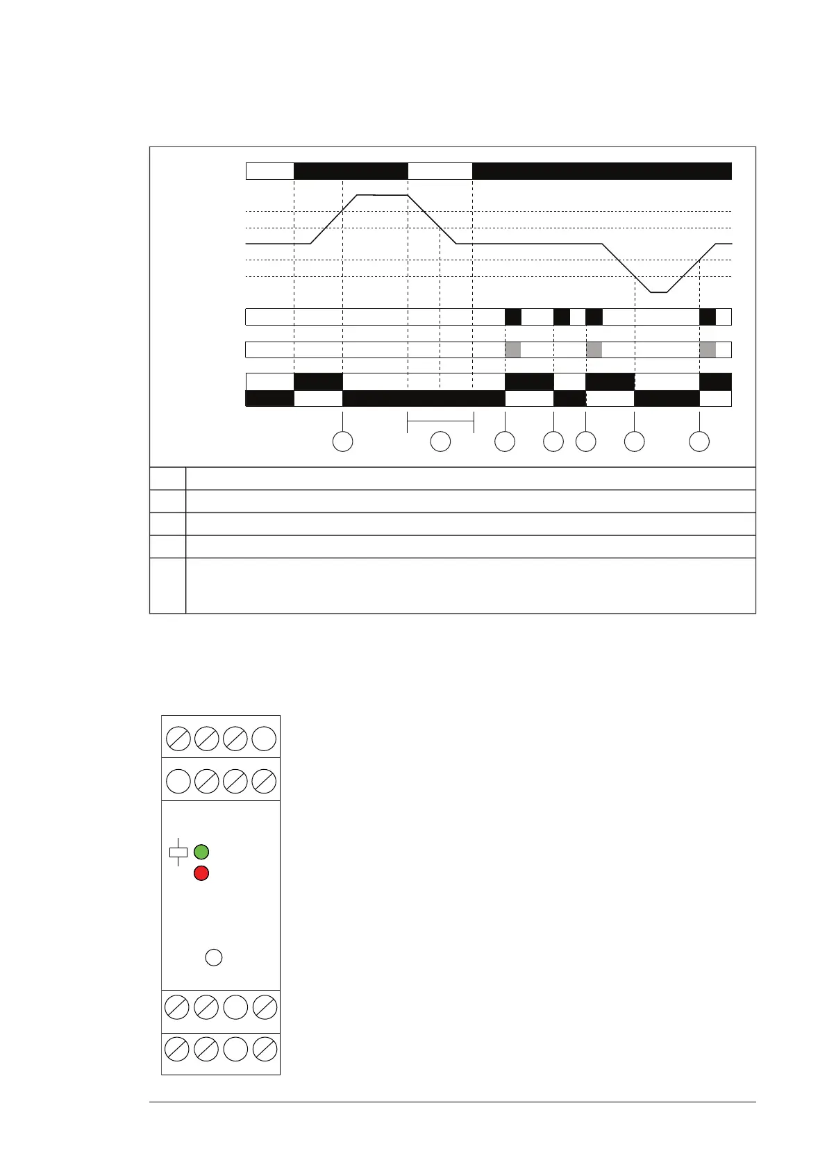
Operation diagram
A1-A2
2830 Ω
1100 Ω
R [Ω]
19 Ω
12 Ω
Test / Reset
S1-T2
11-14 / 21-24
11-12 / 21-22
1 5
1 5 5 53 42
Tripping caused by overtemperature1
Control supply voltage interrupted2
Test (outputs are switched off)3
Short-circuit in sensor circuit4
Reset (resets fault)5
• Manually with a front-face Test / Reset button
• Externally by a remote reset between terminal S1-T2
■ DOLD MK 9163N.12/110-ATEX thermistor relay
Layout
Power supplyA1-A2
A1 (+) 11 21
P1 P2 X1
R
Test /
Reset
22 24 X2
12 14 A2
Measuring circuit with 1…6 sensorsP1-P2
Remote reset push button switchX1-X2
Output contacts (1)
• 11: Common
• 12: Normally-closed
• 14: Normally-open
11-12/14
Output contacts (2)
• 21: Common
• 22: Normally-closed
• 24: Normally-open
21-22/24
Test and internal reset buttonTest / Reset
Supply voltage presentUpper LED
(green)
Fault (overtemperature, broken wire, or short-circuit in the
sensor circuit)
"R" LED (red)
ATEX-certified motor thermal protection function with PTC thermistor relays (+L513+Q971) 23
 Loading...