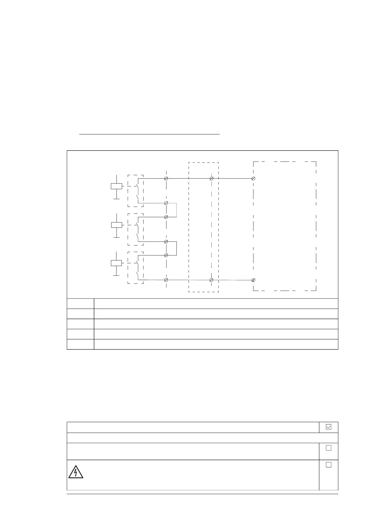
■ Wiring example
In this example, contacts of the Pt100 relay(s) are wired to digital input DI6 of the drive
control unit.
1. Connect the Pt100 sensor(s) of the motor to the relay(s) K71.x (and K72.x, K73.x if
included) to terminal block [X506].
2. Connect a +24 V DC source via contacts 14 and 13 of the extension relay(s) [A81] (and
[A82], [A83] if included) to digital input DI6 on the drive control unit. The contacts are
wired in series.
3. With an FSO module (not shown in the figure): If necessary, connect a reset circuit to
an input of the FSO module (for example, DI X113:2).
ZCU/BCU
13
14
13
14
X506 XD24:7
X504
XD24:7
+24VD
13
14
XDI:6 XDI:6
DI6
A81
(A82)
(A83)
Extension relay, stator windingsA81
Extension relay, bearingsA82
Extension relay, stator windingsA83
Additional I/O terminal block (option +L504)X504
Drive control unitZCU/BCU
See the circuit diagrams delivered with the drive for the actual wiring and terminals. For
wiring diagram examples, see chapter Circuit diagrams.
Start-up and acceptance test
Use the Drive composer PC tool or a control panel to do the start-up and acceptance test.
To set FSO module parameters, you must use the Drive composer pro PC tool.
Action
Initial status
Make sure that the drive is ready for use, that is, you have done the tasks of the drive start-up procedure.
See the drive hardware manual.
WARNING!
Obey the Safety instructions (page 9). If you ignore them, injury or death, or damage to the
equipment can occur.
ATEX-certified motor thermal protection function with Pt100 relays (+L514+Q971) 37
 Loading...