AquaMaster 3 FET200
Electromagnetic flowmeter Transmitter 3 Electrical Installation
OI/FET200–EN Rev. I 17
3.3 Input / Output Connections
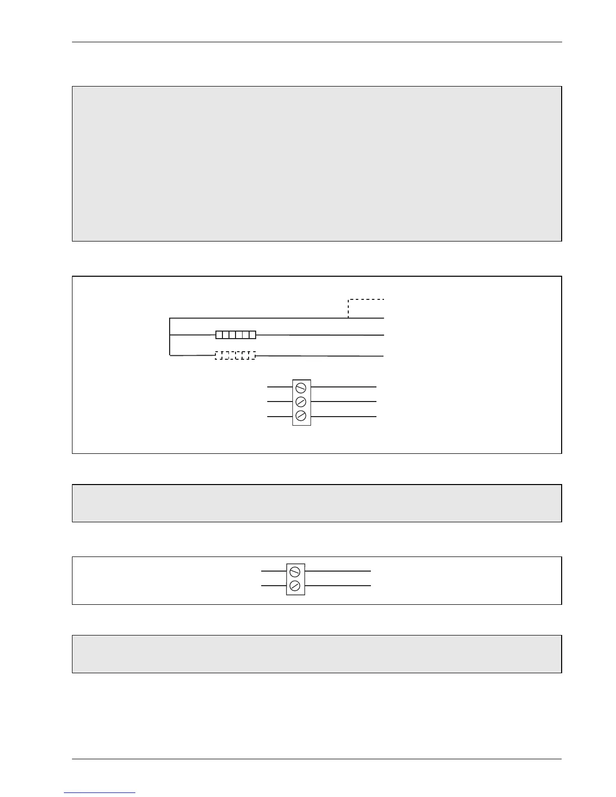
3.3.1 Frequency Outputs
3.3.2 Alarm Interface
Caution.
Refer to the Specification, Section 5, page 34 for input / output ratings.
Inductive loads must be suppressed or clamped to limit voltage swings.
Operation of outputs is programmable – see Programming Guide (COI/FET2XX–EN) for details.
External isolators are not normally required as the pulse and alarm circuit is electrically-separated
from all other AquaMaster3 connections.
Capacitive loads must be inrush current limited.
Fully-floating pulse outputs may be subject to static damage, for example connecting to a floating
datalogger, unless 'COM' is operated within its galvanic isolation range (±35 V) from earth.
Fig. 3.6 Frequency Output Connections
Note. Outputs 1 and 2 are not polarity-sensitive. The common connection for these outputs is
designated ‘COM’.
Fig. 3.7 Alarm Output Connections
Note. Output 3 is not polarity sensitive. The common connection for these outputs is designated
‘COM’.
123456
123456
 Loading...