2
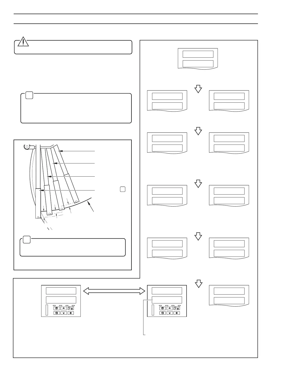
CPU Test carries out check of processor circuitry –
see
Error Codes
below.
Configuration Test carries out check of non-volatile
memories containing the instrument configuration,
then indicates pass or fail – see
Error Codes
below.
Calibration Test carries out check of non-volatile
memories containing the calibration data for each
analog input and output, then indicates pass or fail –
see
Error Codes
below.
Instrument Test identifies the instrument type, e.g.
1914r – see Table 2.1 in the
Installation Manual.
or
or
or
or
Battery Back RAM Test carries out check of battery
back RAM, then indicates pass or fail – see
Error
Codes
below.
Error Codes are
displayed in the event
of a fault – see
Section 2.1.1.
or
Normal Display
A––––F
–2–4––
bb rAM
PASS
bb rAM
FAIL
CAL
FAIL
CAL
PASS
CONFIG
FAIL
CONFIG
PASS
CPU
FAIL
CPU
PASS
1914 r
tESt
AL
RMT
AT
MAN
Lined Failed indicates power failure
and is cleared when advancing to the
next frame or page.
AL
RMT
AT
MAN
Flashing
between
Not applicable on single
channel instruments
!00.3
100.3
LINE
FAILEd
2.1 Instrument Power-up – Fig. 2.1 and 2.2
Caution. Ensure that all connections, especially to
the earth stud, are made correctly.
a) Check that the input sensors are installed correctly.
b) Check that the pen(s) are installed correctly – see Fig. 2.1.
c) Switch on the supply to the instrument, any power-
operated control circuits and the input signals. Wait for the
pens to settle.
✶
Note. On power-up, the pens are moved to an
off-chart position for automatic referencing. Pen
chatter may occur on those pens nearest the
reference position.
This is a normal function of the
instrument.
d) The start-up sequence shown in Fig. 2.2 is displayed on
faceplate 1 when the supply is first switched on.
✶
Red Pen
(Channel 1)
Green Pen
(Channel 2)
Blue Pen
(Channel 3)
Black Pen
(Channel 4)
0.35 (8.8)
Chart Time Line
Dimensions in inches (mm)
0.175 (4.4)
0.175 (4.4)
2 SETTING UP
✶
Note. If the true time line event option is fitted,
the violet event pen records on the same time line as
the red pen, but on the outer edge of the chart.
Fig. 2.1 Checking the Pen(s) Installation
Fig. 2.2 Instrument Displays at Start-up
 Loading...