NAL/NALF – Mounting and operation manual 13
Testing the interlock
It shall not be possible to close the switch-disconnector when the
earth switch is closed.
It shall not be possible to close the earth switch-disconnector
when the switch is closed.
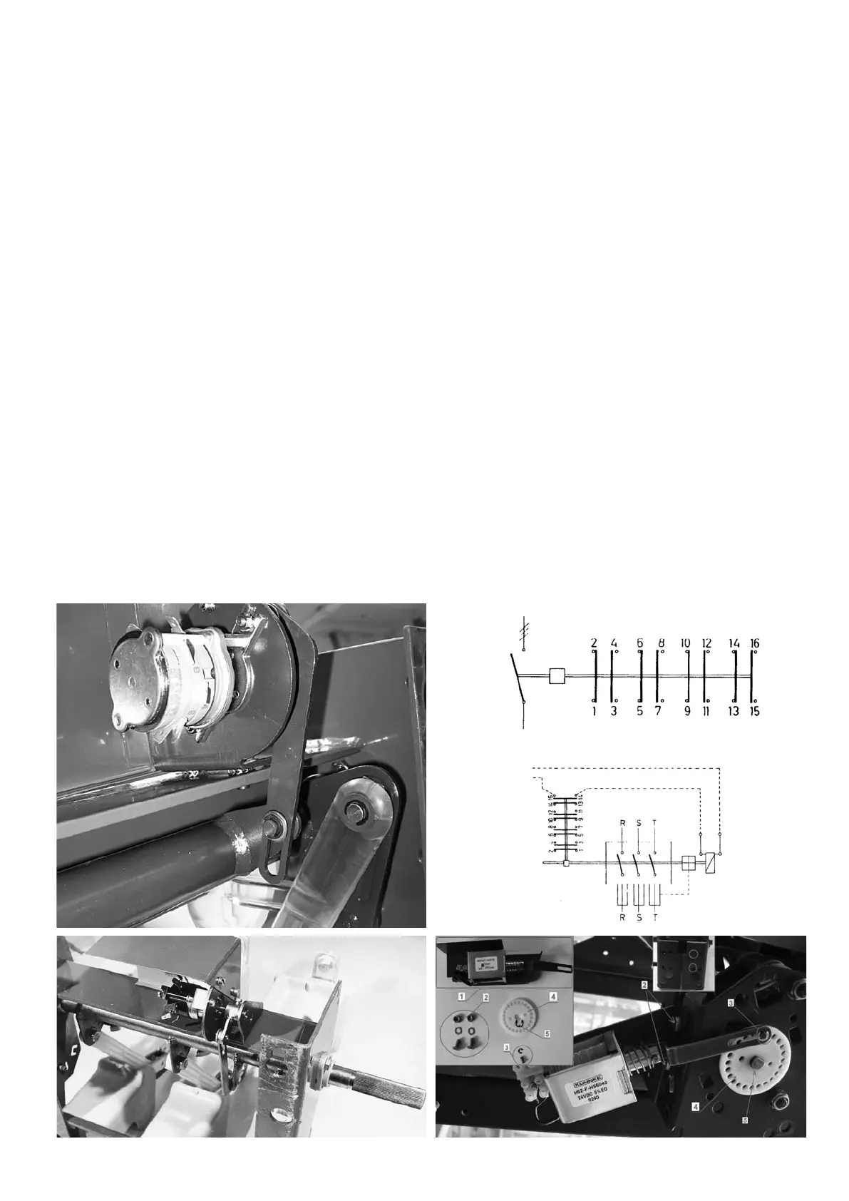
9.0 Mounting the shunt release. Fig. 38
Turn the operating shaft E, see Fig. 26 a maximum of 60°
clockwise. Opening spring housing F, see Fig. 31, must not be
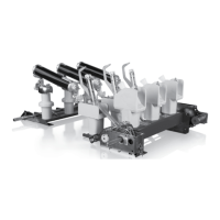
Fig. 35 Auxiliary switch mounted on NAL 17-24 | Fig. 36 Wiring diagram auxiliary switch | Fig. 37 Wiring diagram tripping coil | Fig. 38 Shunt
trip parts component A-mechanism | Fig. 39 Auxiliary switch mounted on NAL 12
Fig. 35
Fig. 38Fig. 39
Fig. 36
Fig. 37
latched. Return the shaft to its neutral position. Connect the bar B
to the perforated disc A, see Fig. 31.
10.0 Mounting the auxiliary switch. Fig. 35 and 39
The auxiliary switch is mounted to the frame on the opening side
of the switch-disconnector and the bar connected to the crank on
the hollow shaft.
 Loading...