NAL/NALF – Mounting and operation manual 5
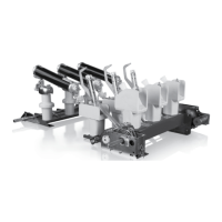
4.0 Mounting the mechanism on the switch. Fig. 4
The mechanisms are mounted on the right hand side of the
switch main frame and the switch is normally operated from the
same side (mechanism-side). When the switches have to be
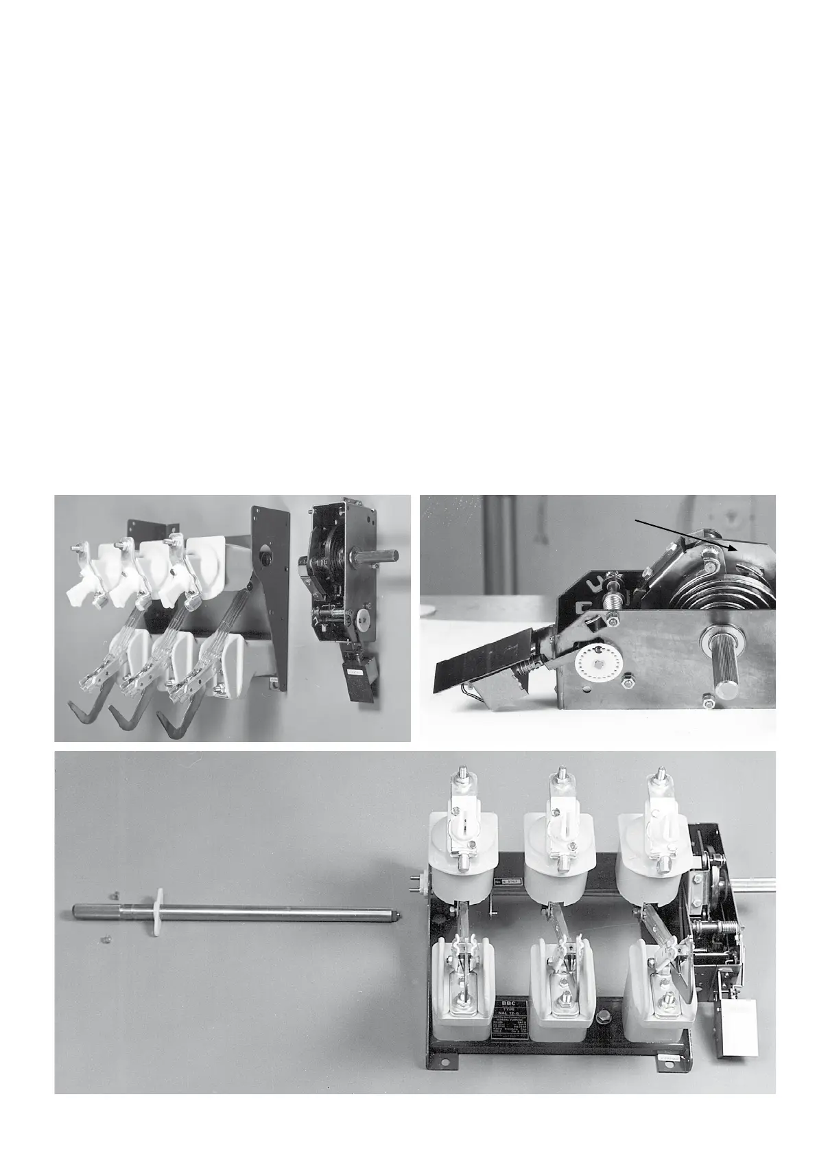
operated from the opposite side, an operating shaft must be con-
nected, see Fig. 6. The mechanism clutch is brought together with
the clutch of the hollow main shaft and the mechanism is fixed to
the switch frame.
Note: Contact knives in open position
Normally the switch disconnector is delivered without shaft exten-
sion for left hand side operation.
4.1. Test operation of A-mechanism
After having mounted the mechanism to the switch frame, check
that the latch H is in correct position by pulling it back to the
outermost position, see Fig. 5.
Test operation see item 2.1.
Fig. 4
Fig. 6
Fig. 5
Fig. 4 Mounting the mechanism on the switch | Fig. 5 Shunt trip mounted on the A-mechanism | Fig. 6 Shaft extension for the
left-hand side operation
H
 Loading...