24 NAL/NALF – Mounting and operation manual
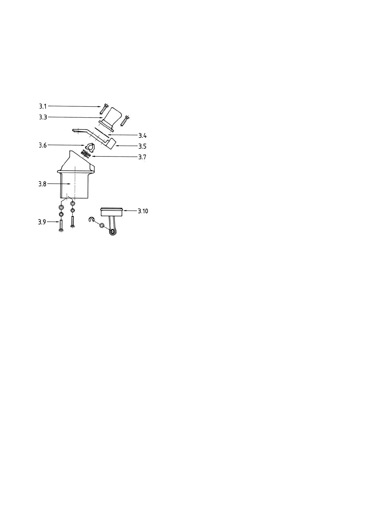
Fig. 70 Hollow insulator complete
14.2 Replacement of fixed contact on the opening side
Fig. 70
Switch-disconnector in open position:
1. Unscrew the two screws 3.1 and lift up the arcing chamber
and the thermal disc 3.4 (for 630 A) while pressing the main
contact 3.5 firmly against the hollow insulator 3.8.
2. Lift up the main contact 3.5 by the arcing contacts 3.6 which
penetrate the main contact. Remove the pressure spring 3.7
and clean the top of the insulator and the hole, and blow out
the threaded holes (use eye protection).
3. Attach the new main contact in reverse order as described
above.
Demaged parts must be replaced:
– take care that the arcing contacts 3.6 are correctly placed
in the pressure spring 3.7,
– by mounting the termal disc 3.4 and the arcing chamber
3.3, the main contact 3.5 must be pressed firmly against
the hollow insulator 3.8. Attach the whole assembly by the
screws 3.1. For correct torque see page 29.
Check correct position of the arcing contact and test correct
function. Grease the contact area with ISOFLEX TOPAS
NCA 52.
15.0 Replacement of the arcing chamber. Fig. 70
Follow instructions under item 14.2.
16.0 Replacement of insulators
16.1 Hollow insulators with arcing chamber. Fig. 70
1. Unscrew 3.9 and detach the insulator.
2. The new insulator has to be insulator inside with a film of
silicone, type DC200 Fluid 100 cst.
3. Attach the new insulator to the frame by the two self-tapping
screws.
Remember to mount the piston with piston rod 3.10. For
correct torque see page 29.
Note the washer and spring washer for the screws.
16.2 Pivot side support insulator. Fig. 69
Detach the main contact with contact knives according to item
14.1 point 2.
1. Unscrew 2.5 and detach the insulator,
2. Attach the new insulator to the frame by the two self-tapping
screws 2.5,
For correct torque see page 29.
Note the washer and spring washer for the screws.
3. Attach the main contact with the contact knife to the top of
the insulator and adjust according to item 14.1, page 22.
 Loading...