NPBA-12 Installation and Start-up Guide 3-1
Chapter 3 – Mechanical Installation
Overview
This chapter contains module mounting instructions. Depending on the
drive, the module can be installed either inside or outside the drive
housing or cabinet. See the user’s manual of the drive for module
placement options.
Mounting Outside
the Drive
Choose the location for the module. Note the following:
• The cabling instructions in Chapter 4 must be followed.
• The ambient conditions should be taken into account (see
Appendix D). The degree of protection of the module is IP 20.
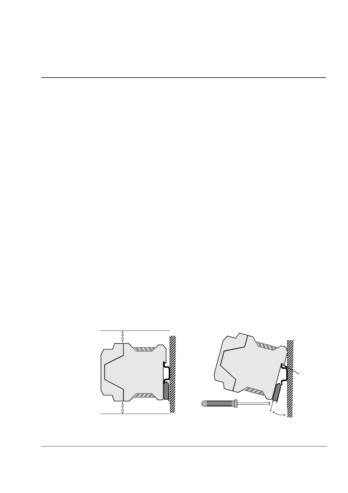
• Observe the free space requirements for the module (see the figure
below) and the drive (see the drive documentation).
• Module earth is connected to the mounting rail by means of an
earthing tab (see the figure below). The mounting rail onto which the
option module is to be mounted must be earthed to a noiseless
earth. If the rail is not mounted on a properly earthed base, a
separate earthing conductor must be used. The conductor must be
as short as possible and its cross-sectional area must be 6 mm
2
at
least. Note: No solid copper conductor may be used (stranded wire
allowed only).
Mounting instructions:
1. Switch off all dangerous voltages in the enclosure that the module
is to be mounted in.
2. Fasten the rail and ensure the proper earthing as described above.
3. Push the module onto the rail. The module can be released by
pulling the locking spring with a screwdriver (see below).
Earthing
Tab
10 mm
10 mm
 Loading...


