Chapter 4 – Electrical Installation
NPBA-12 Installation and Start-up Guide 4-3
NPBA-12 Connections
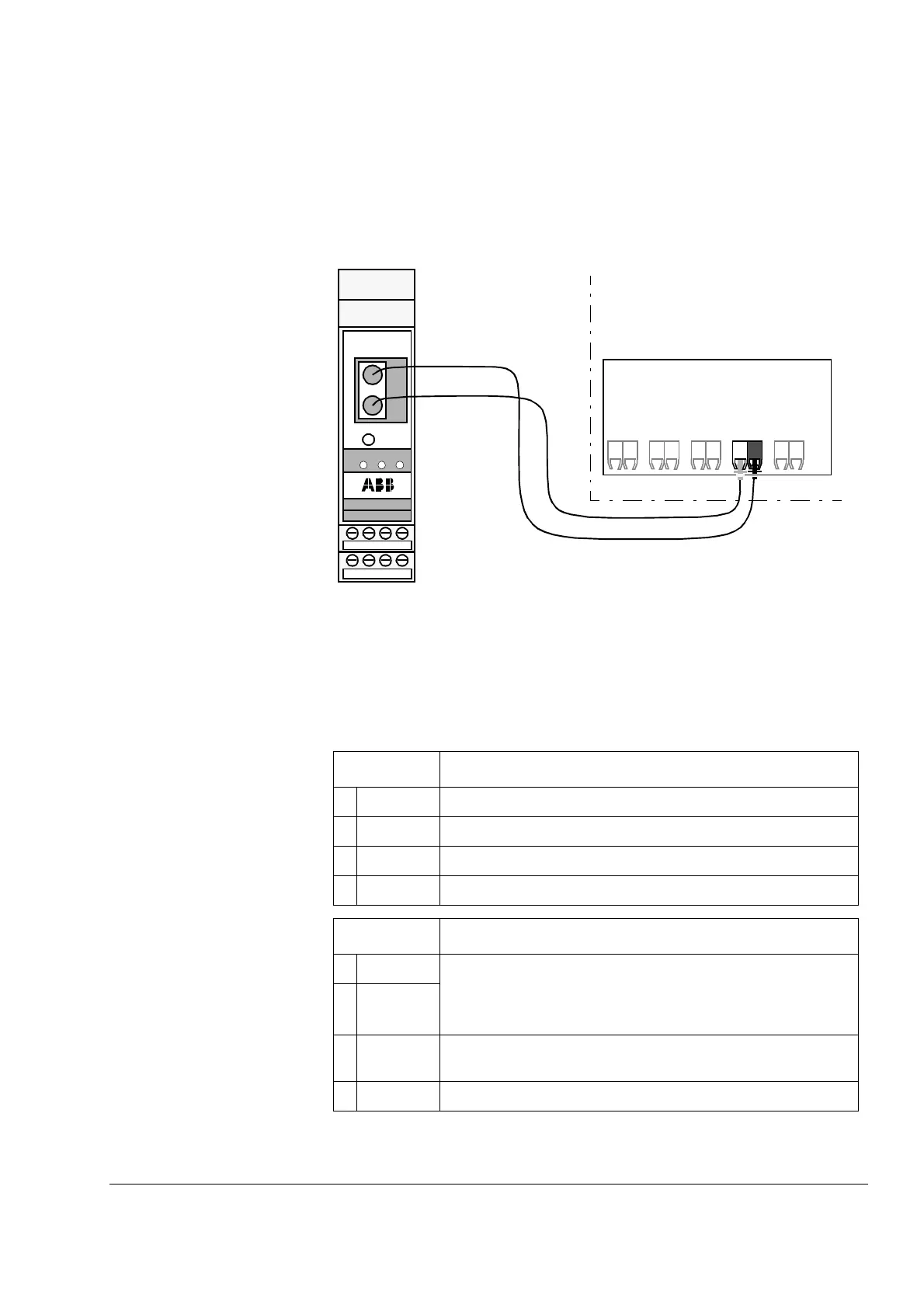
Drive Connection The NPBA-12 module is connected to the drive using a fibre optic cable
link. Consult the drive documentation as to the corresponding terminals
inside the drive.
Figure 4-2 Fibre optic link connecting the NPBA-12 to the drive.
PROFIBUS and Power
Connections
The bus cable and the external power supply are connected to terminal
blocks X1 and X2 on the NPBA-12.
The terminal blocks are described below.
X1 Description
1 A Data Negative (Conductor 2 in twisted pair).
2 B Data Positive (Conductor 1 in twisted pair).
3 A Data Negative (Conductor 2 in twisted pair).
4 B Data Positive (Conductor 1 in twisted pair).
X2 Description
5 +24V Power supply for the module (24 V d.c. ±10%).
The power can be taken from the drive’s internal power supply
(see drive manuals), or an external power supply.
On-board power supply shuts off if the voltage drops below 11 V.
60V
7 DG PROFIBUS cable data ground (optional 3rd conductor).
Connected to module earth via a 1 MΩ/15 nF RC network.
8 SH PROFIBUS cable shield. Internally connected to module earth.
NPBA-12
PROFI BUS ADAPTER
MAST ER
AB
+24V 0V DG SH
RESET
TXD
RXD
5
678
1234
MSG DDCS
AB
ABB Drive
RTT
DDCS
 Loading...


