14 2TLC172001M0211_A
4.3 Analogue inputs
4.3.1 Analogue inputs 0-10V / 4-20mA (Pluto D20 and D45)
Pluto D20 is equipped with 4, and Pluto D45 with 8, safe 4-20mA/0-10V analogue inputs.
These (D20: IA0 – IA3, D45: IA0 – IA7) can be configured as either “ordinary” failsafe inputs,
as analogue inputs 0-10V or as analogue inputs 4-20mA. (For D45 IA0 – IA3 can also be
configured as counter inputs, see below.) For an application to reach SIL 3/PL e it is required
that two sensors in parallel with one input each are being used. See Pluto Programming
Manual.
4.3.1.1 Safety in application
Each input is connected to both processors in order to be able to use them as standalone
safety inputs. There are however some faults which can give failure in the measurement such
as interruption in the connector block, or interruption in the cabling between sensor and Pluto
which leads to that Pluto reads a value close to 0.
To achieve higher degree of safety or redundancy for a complete application there are some
requirements and suggested solutions.
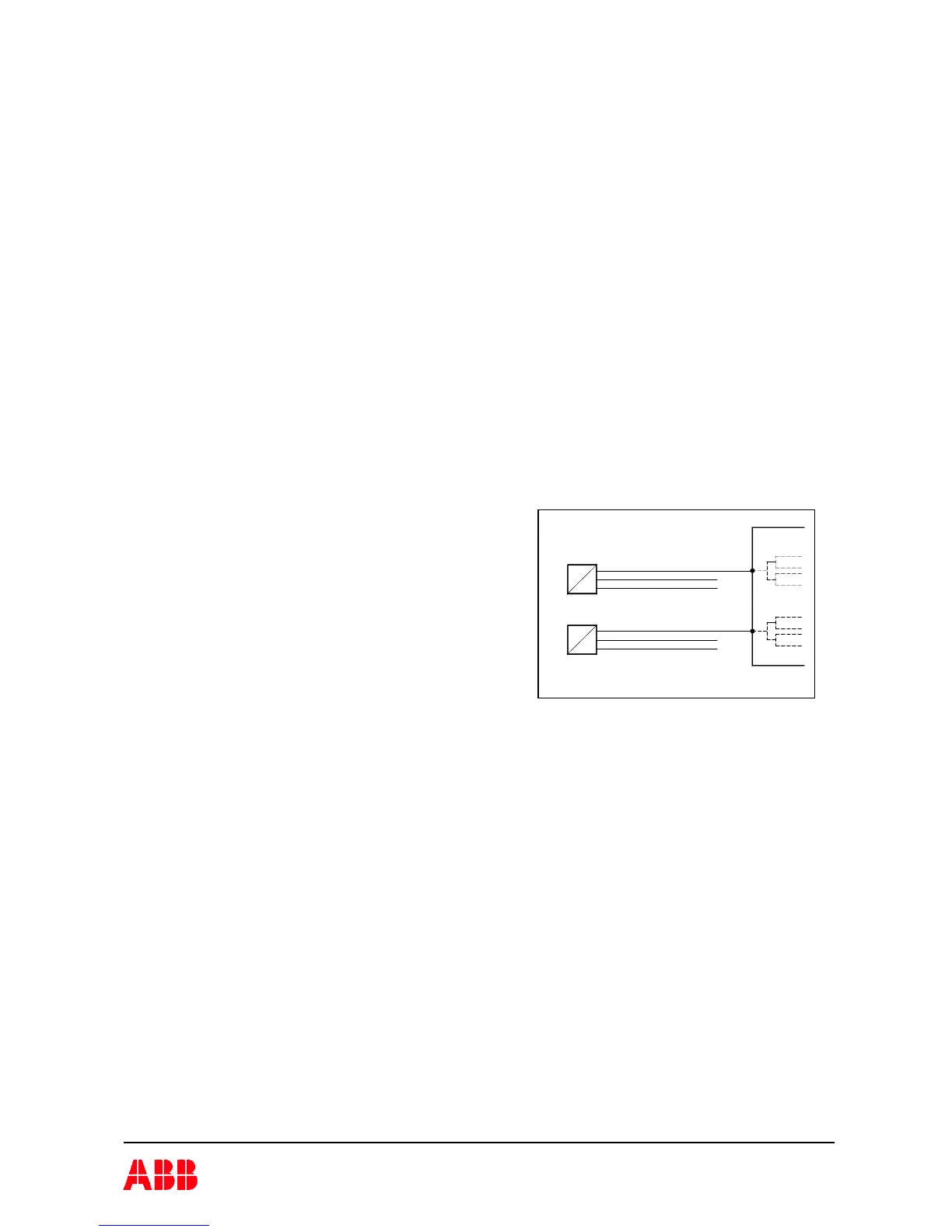
4.3.1.1.1 Dual channel solutions
A complete dual channel application with two
sensors using two inputs, one for each sensor and
the sensor values are compared with each other, the
application can achieve category 4/PL e and SIL 3.
In general the physical values must be dynamic and
must not be static. In case that the physical values
are almost static, then for category 4 a test must be
performed daily. If not, the solution can only be
regarded as category 3/PL d.
In the application there is normally some trip out function when a limit value is passed, such as
over temp, overpressure etc. Since there in process industry are applications which do not trip
out under normal operation a test procedure should be implemented, especially for test of the
sensors. Such test can be a manual test once a year.
4.3.1.1.2 Single channel solution
A safety function with a single sensor using a single input gives category 2, PL b..c,
SIL 2. Factors which have influence on the safety level are:
- If there is a dynamic behaviour in the application that is predictable.
- If wire break or other interruptions of the signal is detected. Input values close to 0V and
0mA can be used as fault condition by using for example 4..20mA as correct values.
- If the sensor value can be compared with another value from another source. (This can
however be seen as a dual channel solution.)
- If automatic test procedure can be implemented.
- Protected cables. The cables can be protected against mechanical damage and separated
from other cabling.
- FS-type approved sensor.
A maximum of Category 2, PL d, SIL2 is achievable with approved sensors.
Sensor B
IAx
+24V
0V
µB
µA
Pluto
0V
+24V
IAx
µB
µA
=
4..20mA / 0..10V
4..20mA / 0..10V
=
Sensor A
Dual channel application