22 2TLC172001M0211_A
4.5 Failsafe outputs
4.5.1 Relay outputs
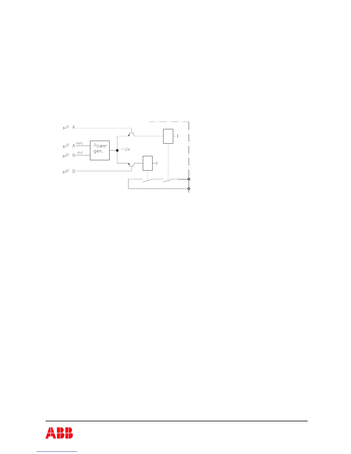
Each potential free relay output is made individually “redundant” by the use of two series
connected relay contacts controlled by each processor. A single output can be used to
individually control a safety function, however the outputs cannot detect short circuits in e.g.
connection cables. In addition to the output relays being controlled by separate processors the
power to the relay coils are generated by “charge” pumps. (For description of function of
“charge” pump see section on failsafe solid state outputs).
4.5.2 Solid state safety outputs
Each digital failsafe output is individually safe and can therefore be used to individually control
a safety function. The nominal output voltage is –24V DC. The negative potential is due to the
“charge” pump principle used. The “charge pump” is designed in such a way that the output
voltage is generated by a capacitor which is charged and discharged by two transistors.
The transistors switch alternately. One transistor switches to plus potential (+), charges the
capacitor and then switches off. The other transistor then switches on discharging the capacitor
to 0 Volts. During the discharge phase the capacitor “sucks” current from the output making the
output a negative voltage. This design principle requires that all components work and change
state in the correct phase. A fault in any component leads to an immediate cessation of output
current generation.
An advantage of using a negative output potential is that it is not normally present in a control
system. Since the output is monitored, Pluto can detect short circuit between the output and a
foreign potential.
Principle for relay outputs
 Loading...