39 2TLC172001M0211_A
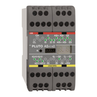
9 Pluto bus communication
Up to 32 Pluto units can be interconnected with CAN-bus. Communication is achieved by
connecting a twisted pair cable to the CH and CL terminals. When this connection is made the
Pluto units can read each other’s I/O.
When the bus is connected each Pluto unit executes its own individual program and operates
independently, however it can read other units I/O.
An interruption of the bus connection results in the I/O in the unit with which communication is
lost, being regarded as a “0” condition by other units on the bus. In this situation all units will
continue program execution with the consequences of the fault being dependent upon the
application program. For instance, if an emergency stop button connected to one unit is used
by another unit as a condition for setting an output, the output will switch off if communications
are lost. Outputs generated by I/O connected directly to a unit are not affected by interruption
of communications.
9.1 Bus cabling
The maximum length of CAN-bus cabling is dependent on the transmission speed. At the
default setting of 400 kbit/s the maximum total length is 150 meters. (This length can be
extended by the use of Gateways as bridges. See Pluto Gateway Manual chapter 1 “General”
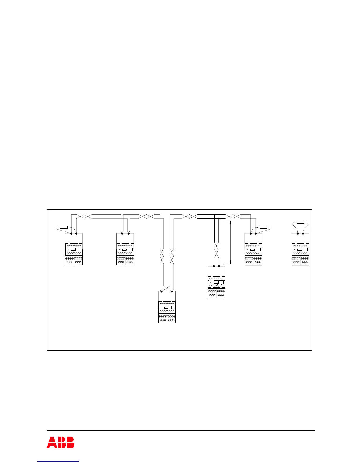
and chapter 8 “CAN bridge mode”). At each end of the bus a termination resistor of 120 W must
be installed. When a Pluto unit is working alone and no bus-cable is connected, it must still be
equipped with a termination resistor.
The bus connection should be made with a twisted pair cable to the CH and CL terminals.
120 W 120 W
120 W
IQ12 IQ14 IQ16 Q0 Q1
PLUTO
K
CL
CH
Q2I6 IQ1 0
Q3IQ11I7I5
I3I1C H
I2C L I0 I4
+24VID 0VIQ17IQ15IQ13
IQ 12 IQ1 4 IQ1 6 Q0 Q1
PLUTO
K
CL
CH
Q2I6 I Q10
Q3
IQ 11I7I5
I3I1C H
I2
C L
I0 I4
+24VID 0VIQ17IQ15IQ 13
IQ12 IQ14 IQ16 Q0 Q1
PLUTO
K
CL
CH
Q2I6 IQ1 0
Q3IQ11I7I5
I3I1C H
I2C L I0 I4
+ 24VID 0VIQ17IQ15IQ13
IQ12 IQ14 IQ16 Q0 Q1
PLUTO
K
CL
CH
Q2I6 IQ10
Q3
IQ11I7I5
I3I1C H
I2C L I0 I4
+24VID 0VIQ17I Q15IQ13
IQ12 IQ14 IQ16 Q0 Q1
PLUTO
K
CL
CH
Q2I6 I Q10
Q3
IQ11I7I5
I3I1C H
I2C L I0 I4
+24VID 0VIQ 17I Q15IQ13
IQ12 I Q14 IQ16 Q0 Q1
PLUTO
K
CL
CH
Q2I6 IQ10
Q3IQ11I7I5
I3I1C H
I2C L I0 I4
+24VID 0VIQ17I Q15IQ13
Stub
Connection of CAN bus: CH to CH and CL to CL.
A terminating resistor in each end of the bus. Stubs are restricted to certain max length and shall not
have terminating resistor.
 Loading...