18 2TLC172001M0211_A
4.4.2 Up/Down count
In order to determine the direction of a movement input IA0 and IA2 can be configured as
Up/Down counters. When this is done the next input (IA1 or IA3) is automatically reserved for
Up/Down counting. This means that for Up/Down counting IA0-IA1 are a pair and IA2-IA3 are
another pair.
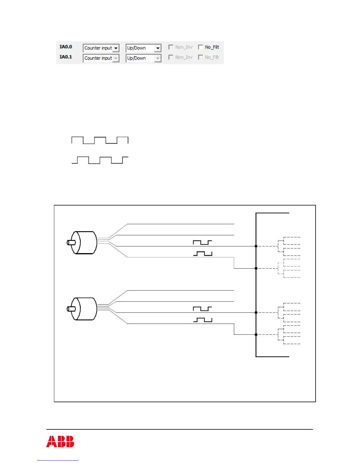
In order to make up/down counting it requires that the sensors can produce A/B-pulses. A/B-
pulses are two square wave signals that are 90° phase shifted to each other. The sensor is
typically a incremental encoder 24V, HTL. For description of the use of Function blocks see
Pluto Programming Manual.
Typical devices are rotary incremental encoders, 24V (HTL).
A
B
Illustration of A and B pulses.
A and B are 90° phase shifted
0V
+24V
IA0
µB
µA
IA1 µA
µB
A
B
A
B
µB
IA3
IA2
+24V
0V
µA
µB
µA
Pluto
Example of speed monitoring with incremental encoders leaving A and B pulses to two inputs, IA0-IA1
or IA2-IA3. The direction is then possible to measure.
Two encoders with two inputs each are used in this example to achieve redundancy.
For overspeed monitoring (safe low speed, SLS) category 4 and PL e is normally reached.
For stand still monitoring Category 3 and PL d can be reached depending on application.
 Loading...