EasyManua.ls Logo

ABB PLUTO Safety-PLC User Manual

ABB PLUTO Safety-PLC
55 pages
To Next Page IconTo Next Page
To Previous Page IconTo Previous Page
Page #21 background imageLoading...
Page #21 background image
21 2TLC172001M0211_A
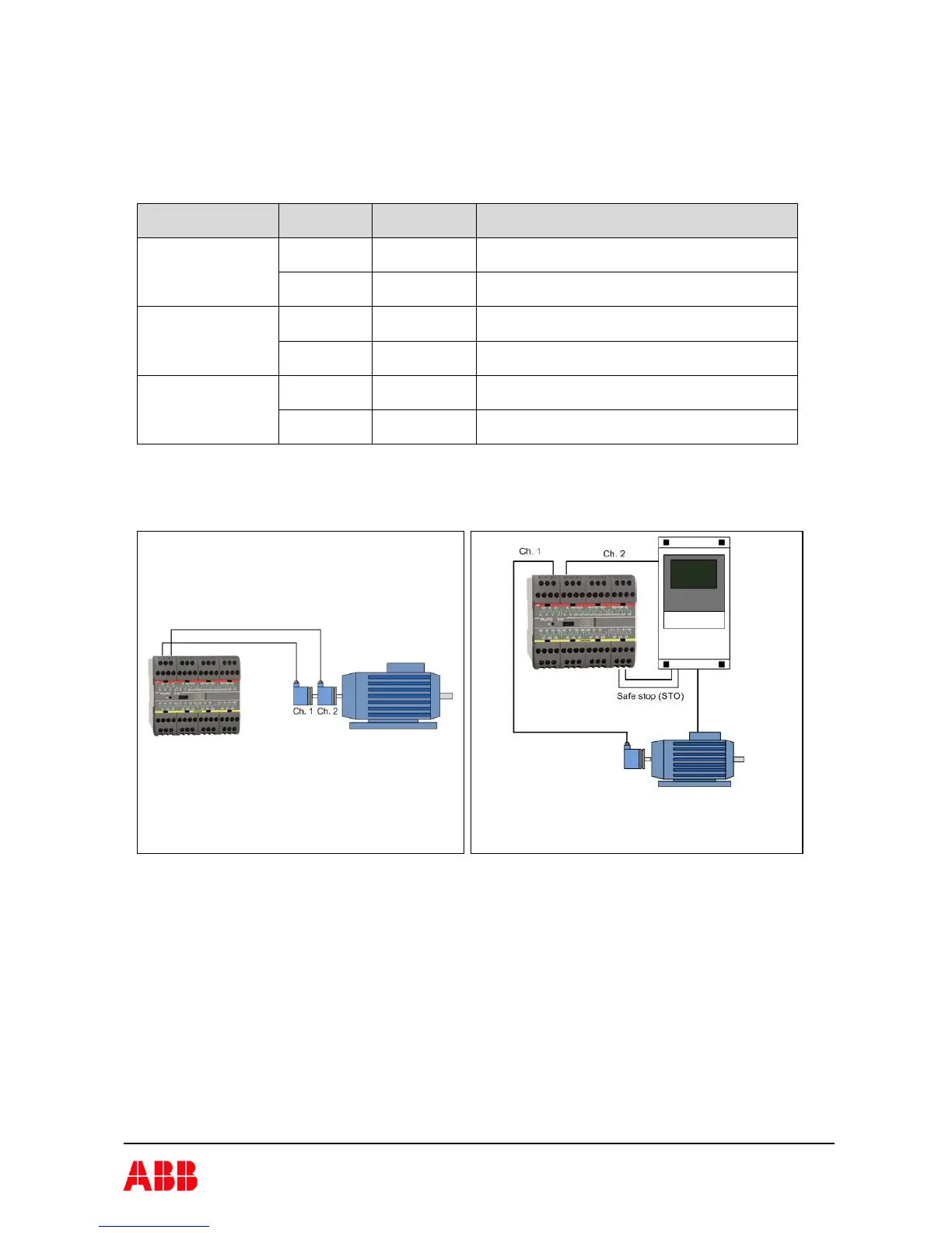
Example with two incremental encoders.
Example of two channel solution with one
encoder and a second channel from a
frequency converter. (Cat 3/PL d/SIL 2)
4.4.7 Possible architectures, achievable safety levels and prerequisites
This table is an overview of safety levels for different applications.
The achievable Cat / SIL / PL depends on the sensor which is used in the application and the
detection capability of faults listed in IEC 61800-5-2, table D.16.
Structure
Achievable
Cat/ PL/ SIL
Prerequisites,
necessary diagnostic to be
realized in the application program
1 sensor/encoder Overspeed Cat 2 / PL c
SIL 1
Monitoring of dynamic behavior.
(E.g. Stand still is off at expected movement)
Stand still
monitoring
Cat 2 / PL c
SIL 1
Monitoring of dynamic behavior. Stand still
should not last in more than approx. 1 hour
2 sensors/encoders
homogeneous
redundant
Overspeed Cat 3 / PL d
SIL 3
Monitoring of dynamic behavior.
(E.g. Stand still is off at expected movement)
Stand still
monitoring
Cat 3 / PL d
SIL 2
Monitoring of dynamic behavior. Stand still
should not last in more than approx. 1 hour
2 sensors/encoders
diverse redundant
Overspeed Cat 4 / PL e
SIL 3
Monitoring of dynamic behavior.
(E.g. Stand still is off at expected movement)
Stand still
monitoring
Cat 3 / PL d
SIL 2
Monitoring of dynamic behavior. Stand still
should not last in more than approx. 1 hour
4.4.7.1 Application examples

Table of Contents

Other manuals for ABB PLUTO Safety-PLC

Question and Answer IconNeed help?

Do you have a question about the ABB PLUTO Safety-PLC and is the answer not in the manual?

ABB PLUTO Safety-PLC Specifications

General IconGeneral
BrandABB
ModelPLUTO Safety-PLC
CategoryController
LanguageEnglish

Summary

General Pluto Safety System Overview

Pluto Electrical Installation Guidelines

Pluto Inputs and Outputs

Digital Failsafe Inputs

Explains how digital failsafe inputs are connected and function.

IQ Terminals: Failsafe Inputs and Non-Failsafe Outputs

Details IQ terminals for failsafe inputs or non-failsafe outputs.

Pluto Analogue Inputs

Covers 0-10V/4-20mA analogue inputs and their safety configurations.

Pluto Failsafe Outputs

Discusses relay and solid-state failsafe output types and their operation.

Pluto Input Connection Guide

Connecting Pluto Safety Devices

Emergency Stop Functionality

Recommendations for testing and maintaining emergency stop functions.

Pluto Output Connection Examples

Pluto Bus Communication

Pluto Programming and Software

Pluto Technical Data and Specifications

Pluto Safety Parameters

Details safety parameters like SIL, PL, and failure rates for Pluto components.

Pluto Message and Fault Code Appendix

Related product manuals