15
1ZSE 5492-118 en, Rev. 4
fm_00013
3 Installation in the transformer
3.1.1 Connection to outside terminals
The connection to terminals for change-over selector, selector switch and current collec-
tor shall follow the connection diagram delivered with the on-load tap-changer. Connection
holes for bolts M10 are Ø11 mm for all terminals.
CAUTION
All connections shall be made carefully and in such a way that there is no risk for them to
come loose. Furthermore, the conductors must not cause mechanical stresses on the out-
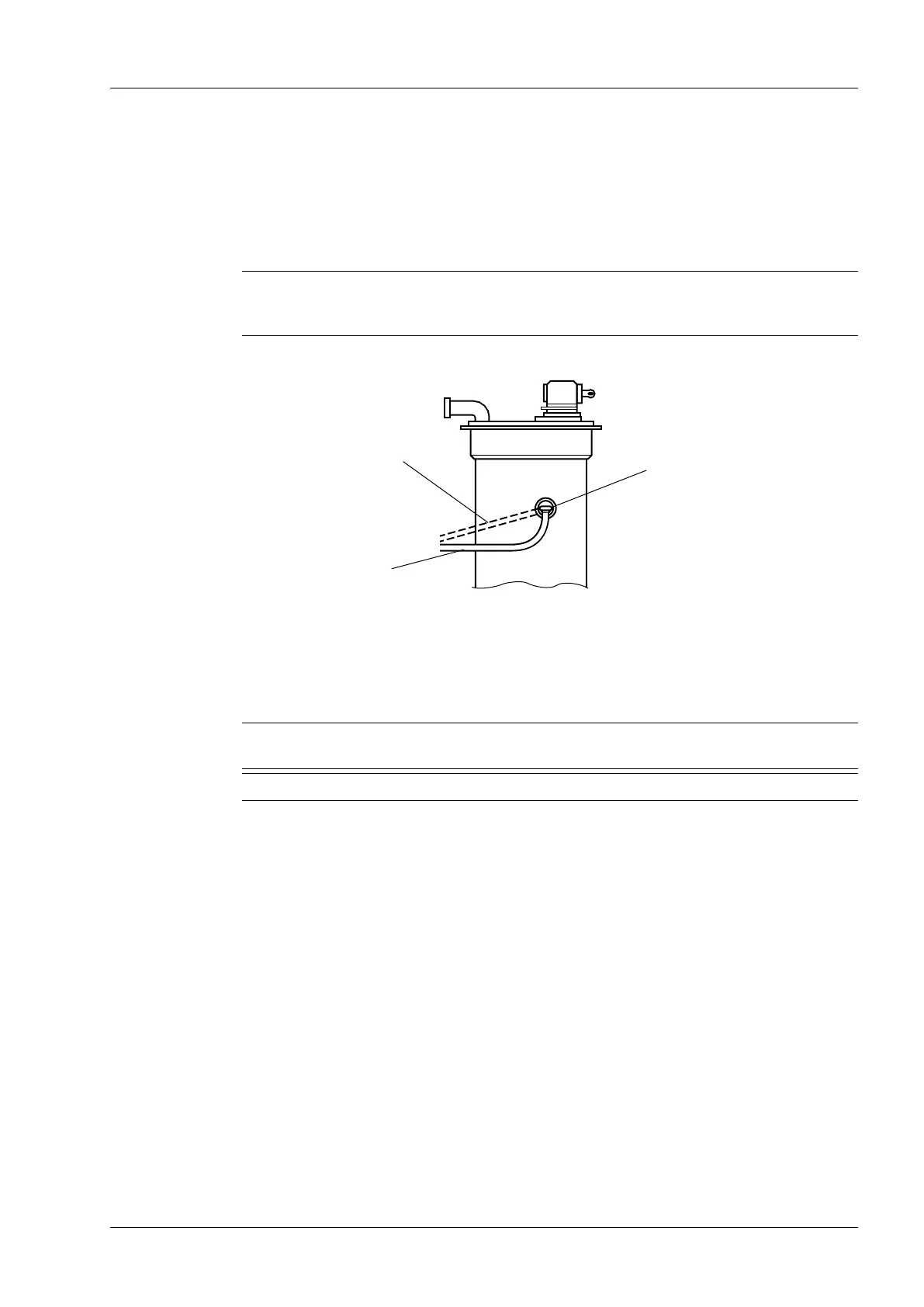
side terminals. Make an expansion bend on every conductor. See Fig. 5.
Wrong
Right
CAUTION
It is recommended that the distance between the cylinder and any conductor is at least
50mm.
The transformer designer is responsible for providing sufcient insulating distances in the oil.
NOTE: There is no need of outer neutral connection leads at UBB.N-types, because
there is already a built-in connection in the on-load tap-changer insert.
Terminal
Fig. 5. Connection to outside terminals.
 Loading...