16
1ZSE 5492-118 en, Rev. 4
fm_00202
3.2 Yoke-mounting
(Pre-mounting on active part of the transformer).
(For cover-mounting, see section 3.1).
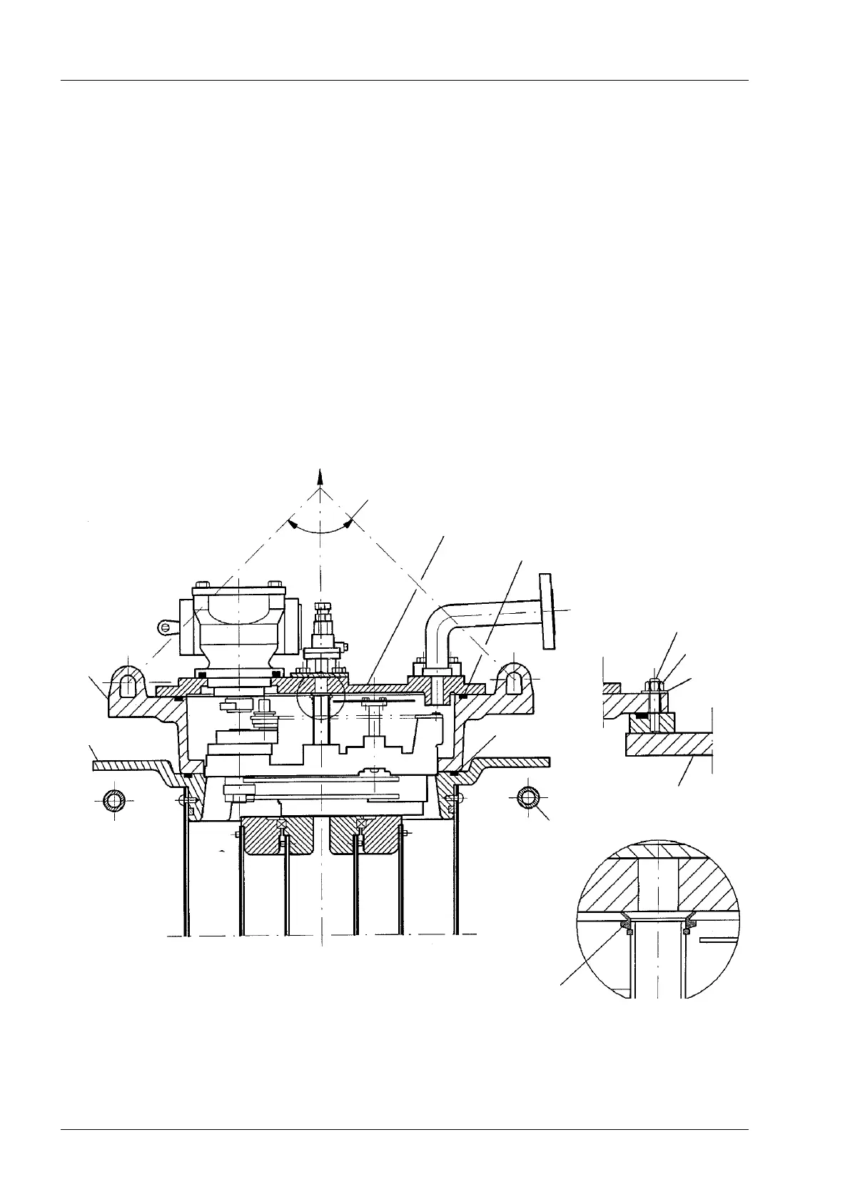
The top section of the on-load tap-changer is designed to be divided into an upper and a
lower ange, see Fig. 6, to t the yoke-mounting.
Before the on-load tap-changer is lifted and attached to the transformer cover it rests on a
fork consisting of two beams protruding from the upper transformer yoke.
NOTE: If guiding pins are used on the fork, they should be insulated with bushings to
prevent circulation currents in the fork when the transformer is in operation.
Mounting of the on-load tap-changer to the ”yoke-fork” can be made according to two alter-
natives depending on when the testing of the transformation ratio shall be performed:
Transformer ratio measurement before drying, see section 3.2.1.
Transformer ratio measurement after drying, see section 3.2.2.
Mounting onto the transformer cover from the yoke, see section 3.2.3.
3 Installation in the transformer
Fig. 6.
Top cover
Washer
Transformer cover
”Yoke-fork”
Lower
part
Upper
part
O-ring
O-ring
”a"
Sealing for the the suction pipe
Max 90
o
Stud
Nut
 Loading...