33
1ZSE 5492-118 en, Rev. 4
5 Final assembly
5.3.2 Mounting of vertical drive shaft
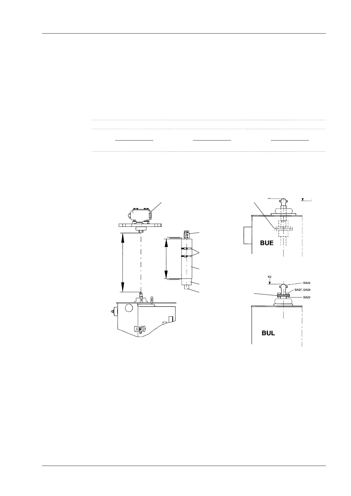
1. Determine the dimension K2 between the spherical shaft ends, see Fig. 24.
2. Cut the vertical square shaft, SA14, to dimension = K2 minus 6 mm. Remove the burrs.
3. Cut the protective tubes SA15 and SA16 so both of them get the same length LB2 ac-
cording to the table 3 below.
Table 3. Length dimensions for LB2.
K2 = 200 to 290 mm K2 = 291 to 600 mm K2 = greater than 600 mm
LB2 =
K2+180 mm
2
LB2 =
K2+220 mm
2
LB2 =
K2+410 mm
2
4. Fit two coupling halves, SA11, on one end of the square shaft with six screws SA12
and washers SA13. Push the shaft to the bottom of the tting in the coupling halves.
Tighten the two screws A rst and then the other. See Fig. 19. Put on the two protective
tubes, SA15 and SA16, and two hose clips SA10. See Fig. 25.
Fig. 24.
SA21
Fig. 25.
SA11
SA14
SA15
SA16
SA10
K2
LB2
Fig. 26.
Fig. 27.
Multiple hole
coupling
Multiple hole
coupling
5. For BUE motor-drive mechanism loosen the two screws in the multiple hole coupling
inside the motor-drive mechanism. See Fig. 26.
For BUL motor-drive mechanism place the multiple hole coupling half (SA 26) on the
coupling half on the outgoing shaft. See Fig. 27.
 Loading...