Operation principle and hardware
description
Contents of this chapter
This chapter gives information about the hardware of the control units.
Hardware description
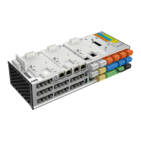
The UCU control units are used for controlling converters via fiber optic links. They
contain integrated branching unit functionality for collecting and storing real-time
data from the modules to help fault tracing and analysis. The data is stored on the
microSDHC memory card inserted into the microSD card slot in the UMU-01 memory
unit and can be analyzed by ABB service personnel.
The control unit requires an external 24 V DC power source. It has three option slots
for I/O extensions, encoders and fieldbus adapters, and a removable memory unit. If
you need to replace the control unit, you can keep the parameter settings by moving
the memory unit from the defective control unit to the new one. The control unit also
has one option slot for connecting a RDCO-0x DDCS communication option board.
The drive-to-drive link (XD2D) is a daisy-chained RS-485 transmission line that allows
basic master/follower communication with one master and multiple followers. The
control unit has two Ethernet ports for control network and two Ethernet ports for
tool/gateway network. The control unit also has a connection for control panel. The
X485 connection provides a connection for optional CIO-01 I/O module. Environmental
sensors measure humidity and temperature.
2
Operation principle and hardware description 9
 Loading...