EasyManua.ls Logo

ABB UZE User Manual

ABB UZE
44 pages
To Next Page IconTo Next Page
To Previous Page IconTo Previous Page
Page #16 background imageLoading...
Page #16 background image
16
1ZSE 5492-115 en, Rev. 5
fm_00071
4 Installation on the transformer
4. Installation on the transformer
CAUTION
The on-load tap-changer must not be included in the drying process of the transformer.
The on-load tap-changer is either bolted or welded to the transformer tank, see
section 4.1.
NOTE: In the event of the on-load tap-changer being delivered without a tank, the
transformer manufacturer has to make the tank and mount it onto the transformer
tank; or make the on-load tap-changer tank integrated with the transformer tank.
Appendix A includes a welding and mounting instruction. In this case, continue with
section 4.2 directly.
4.1 Attaching the on-load tap-changer to the transformer
4.1.1 Welding
For welding the on-load tap-changer to the transformer tank, use llet weld with a ≥ 4 mm
(Fig. 6).
4.1.2 Bolting
A set of cork-rubber gaskets is provided to seal against the transformer tank.
When you install the on-load tap-changer, the gasket should be glued as described below.
Tighten the bolts by approximately 90 Nm torque.
Ensure that the surfaces being in contact with the gaskets are clean and free from grease
and oil.
After cleaning, stick the gaskets to the transformer tank ange (Fig. 7) with ABB glue
13401-608, by brushing glue on both the gasket and the ange.
On-load tap-changer
ange
a ≥ 4 mm
Transformer tank
Fig. 6. Welding detail.

Table of Contents

Other manuals for ABB UZE

Question and Answer IconNeed help?

Do you have a question about the ABB UZE and is the answer not in the manual?

ABB UZE Specifications

General IconGeneral
BrandABB
ModelUZE
CategoryIndustrial Equipment
LanguageEnglish

Summary

WARNING, CAUTION and NOTE

WARNING

Provides information that, if disregarded, could cause injury or death.

CAUTION

Provides information that, if disregarded, could cause damage to the equipment.

Safety precautions

During drying of the transformer

Mounting of gaskets

During oil filling

After oil filling

During service

1.4 Oil conservator

1.7 Tightening torque

3. Drying

4. Installation on the transformer

4.1 Attaching the on-load tap-changer to the transformer

Methods for securing the tap-changer to the transformer tank.

5. Pressure relay

5.3 Checking when commissioning the transformer

Procedure for testing the pressure relay during commissioning.

6. Oil filling

7. Electrical connection and testing

7.2 Connecting and testing

Connecting power and performing operational tests.

7.3 Electrical tests on transformer

Performing acceptance and commissioning tests.

8. Transport

9. Commissioning

9.3 Electrical connection and testing

Performing final electrical connections and tests.

9.4 Putting into operation

Final steps to put the equipment into operation.

APPENDIX A. Welding and mounting instruction

A3 Welding and mounting instruction

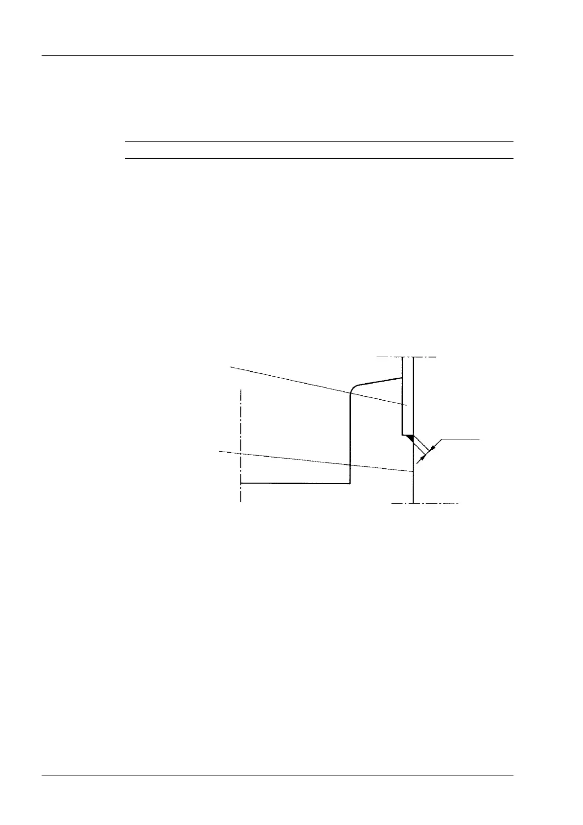
Detailed steps for welding and mounting.

A3.2 Installing the on-load tap-changer and the motor-drive mechanism in the tank

Steps for installing both major components into the tank.

Related product manuals