31
1ZSE 5492-115 en, Rev. 5
fm_00074
A2 Receiving
Do not break the plastic bag until the tap-changer shall be mounted!
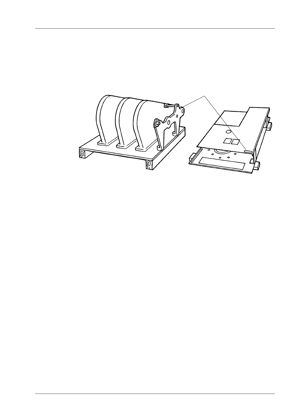
Check that the serial numbers of the on-load tap-changer and the motor-drive mechanism
are the same.
Appendix A
2 Receiving – 3 Welding and mounting instruction
A2.1 Temporary storage before assembly
If the on-load tap-changer is not to be installed on the transformer immediately, once the
delivery has been approved the on-load tap-changer must be kept warm and dry. Let the
unit be kept in its plastic enclosure and leave the drying agent until assembly.
A3 Welding and mounting instruction
Weld the frame and ange to t the motor-drive mechanism BUF 3. Also t an oil valve for
lling and draining of the oil at the lowest possible position. On top of the tank there should
be a connection to a conservator, and the conservator must have breathing device.
A3.1 Welding of the ange and frame for the motor-drive mechanism
Weld the ange to the end plate of the on-load tap-changer tank. Dimensions A, B, C and
tolerances are shown in Fig. A2 and the accompanying table. Then weld the frame of the
motor-drive mechanism (LL 322 007-F) to the end plate. Finally weld the bracket (LL 114
006-7) to the end plate inside the tank.
Dimensions D and E and tolerances are also shown in Fig. A2.
Fig. A1. Location of serial numbers.
Serial numbers

 Loading...


