35
1ZSE 5492-115 en, Rev. 5
fm_00079
A3.2.2 Installation of the motor-drive mechanism
Fit the O-ring, included in mounting kit LL 322 005-A, to ange (LL 322 006-3,
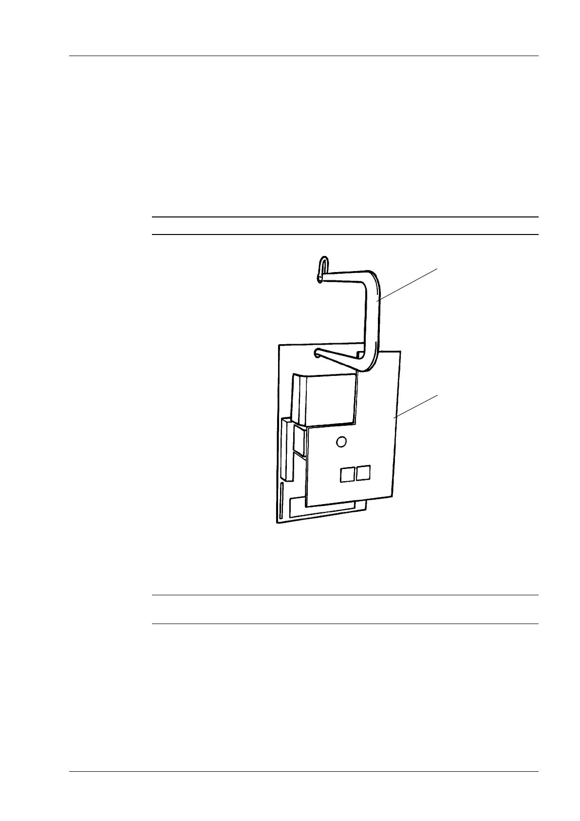
LL 322 006-4 or LL 322 006-5) in the cabinet. Lift the motor-drive mechanism in the hole Ø
40 mm on the frame by the lifting yoke, see Fig. A6, and mount it to the ange in the cabi-
net. Make sure that the driving pin of the on-load tap-changer engages into the slot of the
driving disc of the motor-drive mechanism, see Fig. A7. Secure the motor-drive mechanism
with four M12-nuts and spring washers. When the on-load tap-changer and the motor-drive
mechanism are assembled, remove the locking devices, see Figs. A7 and A8.
WARNING
The motor-drive mechanism must be tted in the slot on the lifting yoke during lifting.
Appendix A
3 Welding and mounting instruction
CAUTION
The locking devices seen in Figs. A7 and A8 must not be removed before the on-load tap-
changer and the motor-drive mechanism have been joined.
Lifting yoke
Motor-drive mechanism
LL 322 004-A
Fig. A6. Lifting of motor-drive mechanism.

 Loading...


