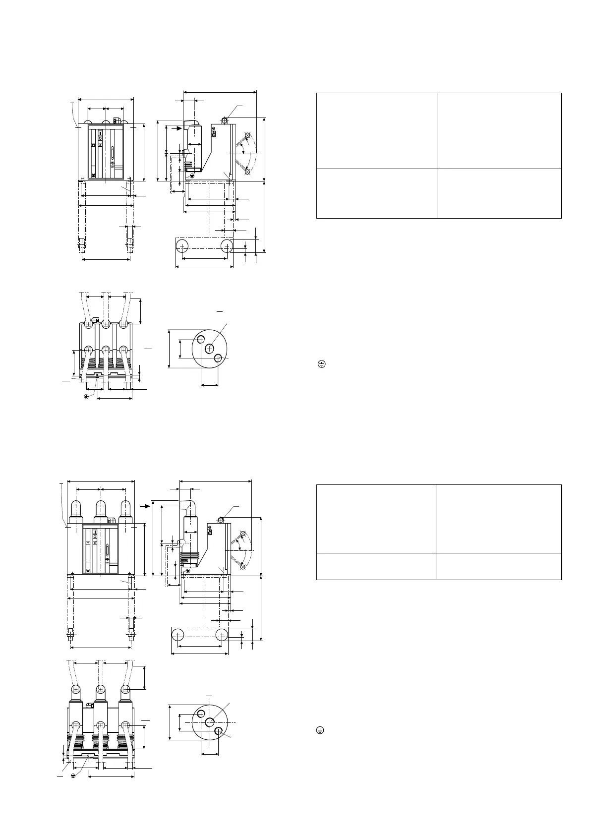
13
K = Cable entry
T = Handling bores, both sides
A = View “A"
GA = Tested terminal zone
M = Minimum distance to DIN VDE 0101
A1 = Terminal for 630 A
A2 = Terminal for 1250 A
A3 = Terminal bar to DIN 46 433,
for 17.5 kV shrink sleeve fitted
= Earthing conductor terminal, use contact washer
Figure 2/10: Dimensional drawing of circuit-breaker type VD4:
• 12 kV, 630 A and 1250 A, ... 31.5 kA
• 17.5 kV, 630 A and 1250 A, ... 31.5 kA
Rated Rated Rated
voltage current short-
circuit
breaking
current
kV A kA p a a
1
cdf
24 630/ ... 25 210 570 515 520 570 390
1250 275 700 645 650 700 488
K = Cable entry
T = Handling bore, both sides
A = View “A"
GA = Tested terminal zone
M = Minimum distance to DIN VDE 0101
A1 = Terminal for 630 A
A2 = Terminal for 1250 A
A3 = Terminal bar to DIN 46 433,
for 24 kV shrink sleeve fitted
= Earthing conductor terminal, use contact washer
Figure 2/11: Dimensional drawing of circuit-breaker type VD4:
24 kV, 630 A and 1250 A, ... 25 kA.
Rated Rated Rated
voltage current short-
circuit
breaking
current
kV A kA p a a
1
cdf
12 630/ ... 31.5 150 450 395 400 450 300
1250 210 570 515 520 570 390
17.5 630/ ... 31.5 150 450 395 400 450 300
1250 210 570 515 520 570 390
A3
200
MM
MM
GA
24
40(50)
f
M12
200
A
ø45
22
22
!
433
T
pp
25
c
a
a1
35
d
VD 4ABB
M12
461
608
95
K
ø115
A
40 °
80 °
M12
205
217,5
77,5
345
409
424
44
550
100
M
30
60
368
480
24
30
475
A1
M12
Insertion
depth 18 + 2
M10
Insertion
depth 15 + 1
A2
M12
f
M
24
M
200
40 (50)
A3
M
M
200
GA
ø45
22
22
A1
M12
Insertion
depth 18 + 2
M10
Insertion
depth 15 + 1
A2
A
25
35
!
c
a
a1
T
pp
433
d
VD 4ABB
631
K
40 °
80 °
M12
310
282,5
77,5
345
409
424
44
550
100
M
30
60
368
480
24
A
608
95
ø115
30
475
M12
2.5 Dimensional drawings
Circuit-breakers for fixed installation

 Loading...