17
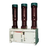
3 Technical Data
Circuit-breakers on withdrawable part
3.1 Technical data and weight
1)
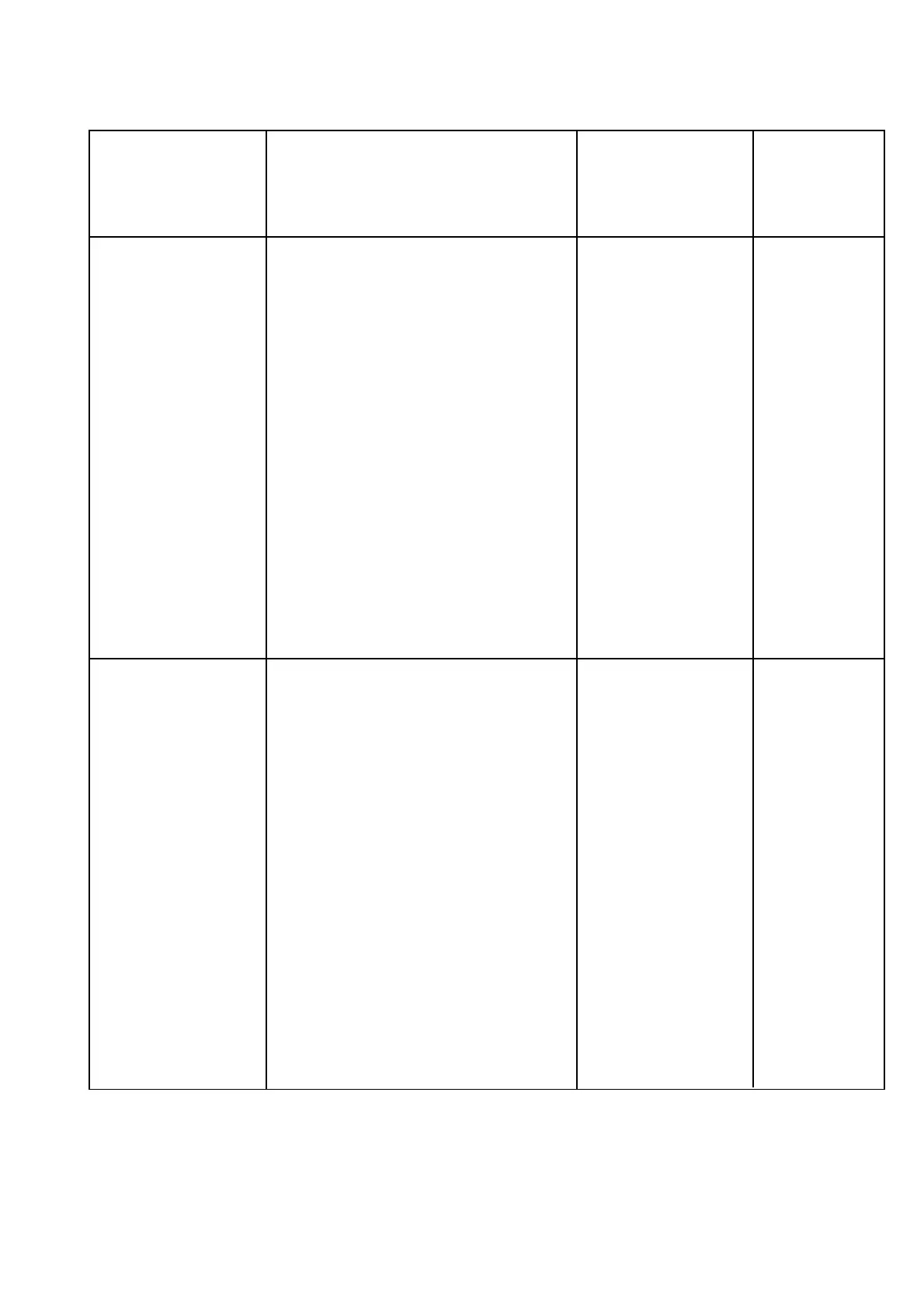
Breaker Rated Rated Rated short- Short- Rated short- Rated short- Pole Weight
1)3)
Permissible number
type voltage current circuit- circuit circuit circuit centres
1)
of vacuum interrupter
breaking breaking making duration switching operations
current current current
symm.
2)
asymm.
2)
(peak)
2)
VM1... kV A kA kA kA s mm approx. kg Figure 2/9 Page 11/12
1206-16 12 630 16 17.4 40 3 150/210 105/110 Diagram A
1212-16 1250 150/210 120/125 Diagram B
1206-20 630 20 21.8 50 3 150/210 105/110 Diagram C
1212-20 1250 150/210 120/125 Diagram D
1216-20 1600 210/275 190/195 Diagram D
1220-20 2000 210/275 195/200 Diagram D
1225-20 2500 275 205 Diagram D
1206-25 630 25 27.3 63 3 150/210 105/110 Diagram E
1212-25 1250 150/210 120/125 Diagram E
1216-25 1600 210/275 190/195 Diagram E
1220-25 2000 210/275 195/200 Diagram E
1225-25 2500 275 205 Diagram E
1206-31 630 31.5 34.3 80 3 150/210 105/110 Diagram F
1212-31 1250 150/210 120/125 Diagram F
1216-31 1600 210/275 190/195 Diagram F
1220-31 2000 210/275 195/200 Diagram F
1225-31 2500 275 205 Diagram F
1212-40 1250 40 43.6 100 3 210 185 Diagram G
1216-40 1600 210/275 190/195 Diagram G
1220-40 2000 210/275 195/200 Diagram G
1225-40 2500 275 205 Diagram G
1706-16 17.5 630 16 17.4 40 3 150/210 105/110 Diagram A
1712-16 1250 150/210 120/125 Diagram B
1706-20 630 20 21.8 50 3 150/210 105/110 Diagram D
1712-20 1250 150/210 120/125 Diagram D
1716-20 1600 210/275 190/195 Diagram D
1720-20 2000 210/275 195/200 Diagram D
1725-20 2500 275 205 Diagram D
1706-25 630 25 27.3 63 3 150/210 105/110 Diagram E
1712-25 1250 150/210 120/125 Diagram E
1716-25 1600 210/275 190/195 Diagram E
1720-25 2000 210/275 195/200 Diagram E
1725-25 2500 275 205 Diagram E
1706-31 630 31.5 34.3 80 3 150/210 105/110 Diagram F
1712-31 1250 150/210 120/125 Diagram F
1716-31 1600 210/275 190/195 Diagram F
1720-31 2000 210/275 195/200 Diagram F
1725-31 2500 275 205 Diagram F
1712-40 1250 40 43.6 100 3 210 185 Diagram G
1716-40 1600 210/275 190/195 Diagram G
1720-40 2000 210/275 195/200 Diagram G
1725-40 2500 275 205 Diagram G
1)
For more details to cell-type allocations see section dimensional drawings.
2)
When the operating voltage is lower than the rated voltage, the same values apply as for rated voltage.
Higher values on request.
3)
With manual charging mechanism.
Weight is increased by around 5 kg if charging motor is fitted.
Weight is increased by around 5 kg if the motor-driven withdrawable assembly is used.

 Loading...