26
3.3 Wiring diagrams for C.B. on withdrawable part
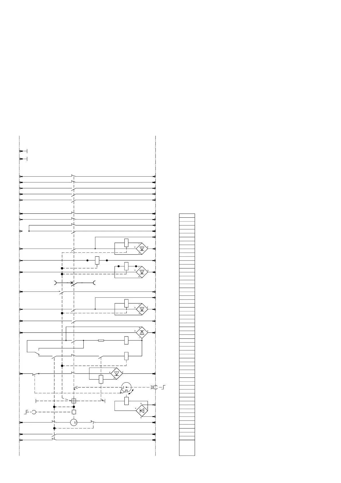
Figure 3/8: Wiring diagram for VD4 vacuum circuit-breaker on manually movable withdrawable assembly.
• Type A of withdrawable part
• Maximum of equipment
• Control wiring plug 58-pole
• Use in panel system ZS, in powerbloc and mounting frame
• Drawing no. GCE2032404
Note:
The wiring diagrams comprise the basic com-
ponents and all further equipment options for the
various VD4 types. The scope of equipment
possible within an individual type series is listed in
the relevant switchgear list, and the euquipment
fitted in each individual case can be found in the
order documentation.
Note:
Please see section 8.5 for explanation to the
withdrawable part
-X0 26 24 25 10 354 27 43 32 31 11 8 23 6 7 9 28 29 401
22
53
5421
-S1
31
32
-
M
0
M
OFF
- S6
3
4
2
1
4
13
14
–K
0
53
54
32
31
S3
22
21
13
14
43
44
-S7
2
1
13
14
-Y7
-S4
13
53 41 31
32
42
54 22
21
-S5
14
44
43
54
53
32
31
22
21
42
41
-Y1
ON
0
-R0
2
-S2
-Y3
-K0
A
41 21 22 18 33 16 17 19 38
39
-Y4 -Y2
-Y2-Y4
-Y9
15 13 37 44 42 302
-V3
-Y9
B
14-X0
-V0
-Y0
-V1
36 46453534 20
E
A
-
Q0
-
X0
P
-Y0 Block Magnet on truck with rectifier -V0
-Y1 Closing block magnet with rectifier -V1
-Y2 1. Shunt release OFF with rectifier -V2
-Y3 Closing release with rectifier -V3
-Y4 Undervoltage release U< with rectifier -V4
-Y7 Indirect overcurrent release
-Y9 2. Shunt release OFF with rectifier -V9
-M0 Charging motor
-K0 Antipumping relay
Mode of presentation:
• Aux. switch -S1 shown for c.b.-mechanism discharged
• C.b.-unit in service position
• Control wiring plug 58-pole
• Earthing switch mechanical interlock with c.b.-unit:
a) C.b.-unit in test position:
Earth. switch can be operated
b) Earth. switch open position:
C.b.-unit can be moved in the service position
-S1 Auxiliary switch on mechanism
-S2 Auxiliary switch on block magnet -Y1
-S3 Auxiliary switch on switch shaft
-S4 Auxiliary switch on switch shaft
-S5 Auxiliary switch on switch shaft
-S6 Auxiliary switch at c.b.-unit
-S7 Fleeting contact 35ms for c.b. tripped indication
See page 54 for comparison of VDE/IEC designations.

 Loading...