24
4. VK906 Control Panel Board
4.1 Description
The VK-906 is designed to offer a user interfaced control panel which passes and
receives signals to and from VL-901 display control board.
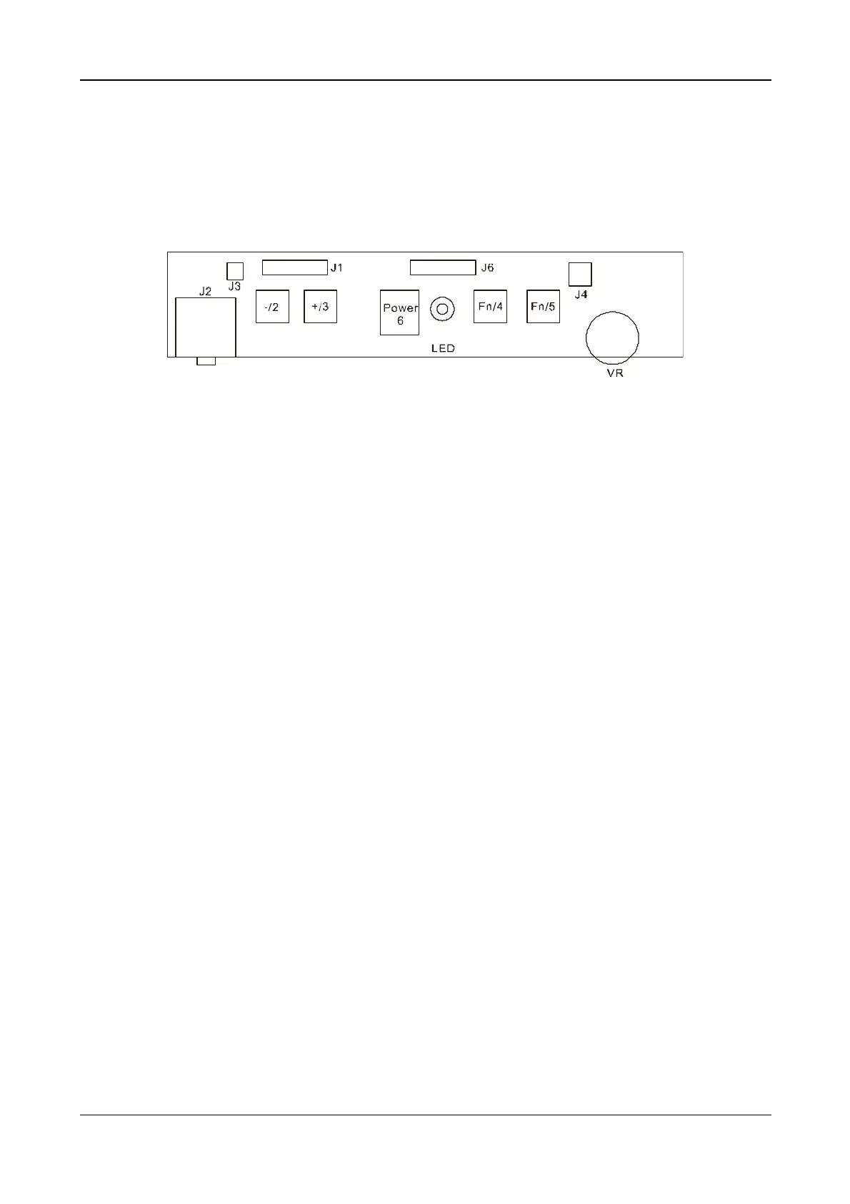
4.2 Connector and Switch Locations
4.3 Connector type
Location Type Maker Number of pins
J1 4500-10 E&T 10
J6 4500-11 E&T 11
J3 87502-0200 ACER 2
J4 87502-0200 ACER 2
J2 SCJ-0348-C SC 9
4.4 Connector pin Assignment
4.4.1 J1
Pin NO. Signal Comment
1 MUTE Audio mute control
2 LED-Y Power saving mode
3 LED-G Monitor is ON
4 GND GND
5 KEY-POWER Power ON/OFF key
6 KEY-DOWN Function select counter-clockwise key
7 KEY-R Adjust up key
8 KEY-L Adjust down key
9 KEY-UP Function select counter-clockwise key
10 GND GND
4.4.2 J6
Pin NO. Signal Comment
1 +5V VDD for Audio Volume Adjustment
2 VR Audio Volume Adjustment
3 L+ Speaker Out L +
4 L- Speaker Out L -
5 MUTE Audio mute control
6 HP-S EAR phone output control
 Loading...