EasyManua.ls Logo

Acer Aspire 1700 Series User Manual

Acer Aspire 1700 Series
119 pages
To Next Page IconTo Next Page
To Previous Page IconTo Previous Page
Page #41 background imageLoading...
Page #41 background image
Chapter 3 47
Disassembly Procedure Flowchart
The flowchart on the succeeding page gives you a graphic representation on the entire disassembly sequence
and instructs you on the components that need to be removed during servicing. For example, if you want to
remove the system board, you must first remove the keyboard, then disassemble the inside assembly frame in
that order.
Start
Base Cover
x7 (fix on base cover)
Battery
Dommy Cover
Dx4
Cx1
Battery
MDC Modem
Card
Optical Drive
Module
(Please see
next page)
Subwoofer
Memory
HDD Module
Thermal
Module (FAN
Sink) w/
screws *4pcs
CPU
VGA Card
(AGP Card)
Wireless Card
Inverter Cover
Cx2
x2
Disconnect
subwoofer cable
Cx2
Cx4
Cx1 Cx4
Cx3
Hinge Cover
Jx4
Upper System
Cover (Middle
Cover)
Keyboard
x6
x4 on rear
Disconnect LED cable
x4
LCD Module
Silicon Line Pad
(LCD Decoration
Bar)
LCD Skirting
Board (LCD
Bezel)
LCD Outer
Shield (LCD
panel)
LCD
Wireless
Antenna
Dx8
Bx2
Bx4
Side Brackets
(LCD
Brackets)
Inverter Board
LED Cable
Ux8
Inverter Board
Brackets
LCD Cable
x2
Remove inverter board mylar
LED Cable
Ox4
LED Board
(Launch
Board)
Disconnect touchpad FFC
Px1
Qx2
Kx5
Mx2
Tx6
Jx4
Dx8
See Next
Page
Disconnect HDD
power cable and
IDE coaxial cable
Rx4
HDD Bracket HDD
Dx6
x4

Table of Contents

Question and Answer IconNeed help?

Do you have a question about the Acer Aspire 1700 Series and is the answer not in the manual?

Acer Aspire 1700 Series Specifications

General IconGeneral
Operating SystemWindows XP Home/Professional
ProcessorIntel Pentium 4
RAMUp to 1GB DDR SDRAM
Storage40GB to 60GB HDD
Optical DriveDVD-ROM, CD-RW/DVD-ROM combo, or DVD-Dual drive
Ports4x USB 2.0, 1x VGA, 1x S-Video
Networking56K Modem, 10/100 Ethernet, Optional 802.11b/g Wireless LAN

Summary

Acer Aspire 1700 Series Service Guide

Chapter 1 System Specifications

Hardware Specifications and Configurations

Detailed technical specifications for processor, BIOS, memory, video, and audio components.

Chapter 2 System Utilities

BIOS Setup Utility

Guide to the BIOS Setup Utility for hardware configuration and system settings.

Chapter 3 Machine Disassembly and Replacement

Disassembly Procedure Flowchart

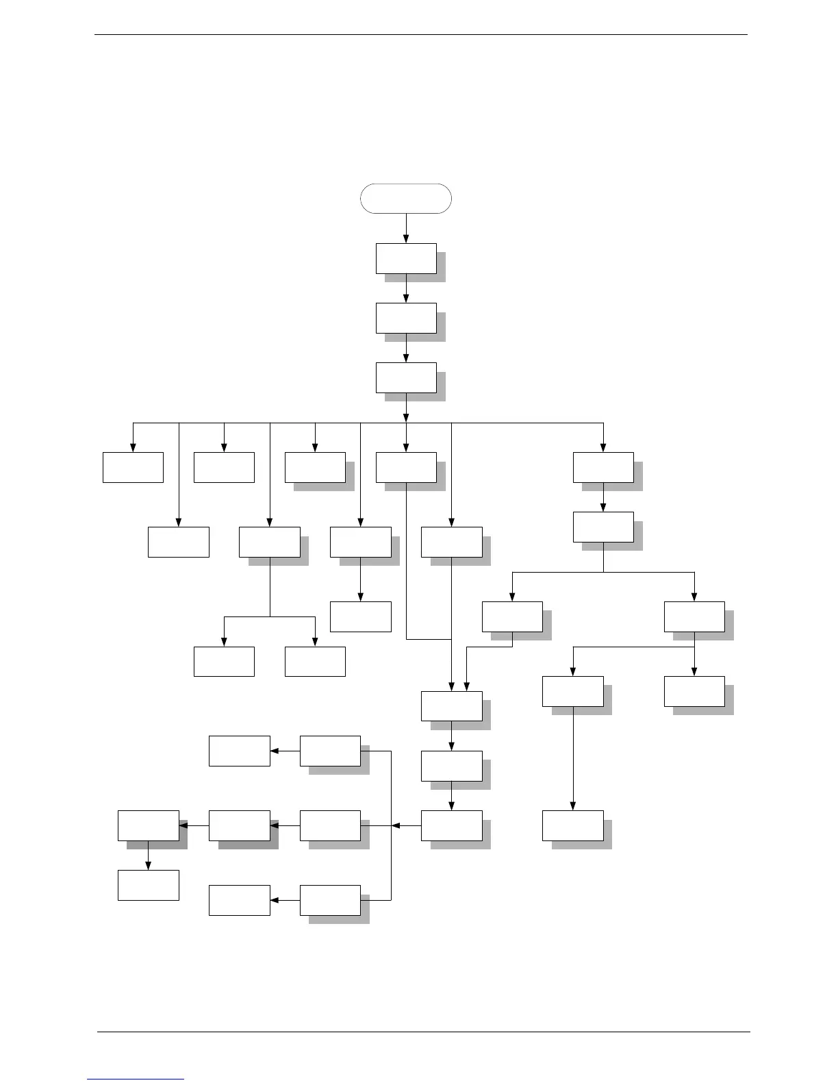
Visual flowchart outlining the sequence of component removal for servicing.

Disassembling

Detailed instructions for removing individual components like battery, HDD, and optical drives.

Re-assembly

Step-by-step instructions for putting the notebook back together after servicing.

Chapter 4 Troubleshooting

System Check Procedures

Procedures for checking specific hardware components like diskette, CD-ROM, and keyboard.

Power-On Self-Test (POST) Error Message

Index of POST error messages and their potential causes and solutions.

Index of Error Messages

A list of common error messages and recommended actions or FRU replacements.

Chapter 5 Jumper and Connector Locations

Chapter 6 FRU List

FRU List

Detailed list of parts, including pictures, part names, and part numbers.

Related product manuals