 Loading...
Do you have a question about the Acer X110 and is the answer not in the manual?
| Display Technology | DLP |
|---|---|
| Resolution | SVGA (800 x 600) |
| Contrast Ratio | 4000:1 |
| Weight | 2.2 kg |
| Brightness | 2500 ANSI lumens |
| Lamp Life | 6000 hours (Eco) |
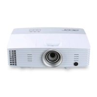
Details projector specifications including dimensions, weight, tilt angle, power supply, and brightness.
Lists supported VGA analog compatibility modes and their corresponding frequency settings.
Provides an outlook of the projector's front and rear sides with labeled components.
Lists necessary tools and provides an initial overview for disassembly and assembly.
Step-by-step guide to removing the projector's lamp cover module.
Instructions for removing the main board and IO cover modules.
Procedure for safely disassembling the LVPS module from the projector.
Guide to accessing service mode and re-writing system/lamp usage hours.
Step-by-step instructions for assembling the lamp driver module.
Procedure for reassembling the IO cover and main board modules.
Instructions for reassembling the projector's lamp module.
Table detailing projector status based on LED indicator lights (Red/Blue).
Lists common symptoms and corresponding troubleshooting procedures.
Lists the necessary equipment for functional testing and alignment.
Procedure to enter and exit the projector's service mode.
Steps to reset the projector's On-Screen Display (OSD) to default settings.
Specifies the environmental conditions and run-in times for testing.
Table outlining inspection checks after changing projector components.
Guide for testing projector functionality via PC connection.
Procedures for PC and video calibration to ensure optimal display.
Tests for CVBS, S-Video, HDTV/Component, and Audio inputs.
Methods for measuring brightness, contrast, and uniformity.
Covers function inspection, factory defaults, and exterior checks.
Lists required software and hardware for firmware upgrading.
Step-by-step guide for installing the DLP Composer Lite software.
Instructions for installing USB drivers for firmware updates.
Detailed steps for performing a firmware upgrade using DLP Composer.
Procedure for downloading waveform data to the projector.
Explains Extended Display Identification Data (EDID) and its purpose.
Lists software and hardware required for EDID upgrading.
Connection steps for setting up the projector for EDID upgrade via VGA.
Step-by-step process for entering EDID information using the program.
Procedure to unlock SNID and reset the default language settings.
Exploded view diagram for the X1161 projector model.
Exploded view diagram for the X1261 projector model.
Exploded view of the projector's engine module.
Exploded view of the projector's lamp driver module assembly.
Defines the format and components of the projector's serial number.
Explains the structure and meaning of PCBA (Printed Circuit Board Assembly) codes.
Lists RS232 commands and their corresponding function features.