26
5-3. SERVICE procedure
The procedure SERVICE can be selected and used only in STB mode. It is used for adjustment
of the zero-signal plate current and the optical sensors disks during repair. We recommend this
procedure to be carried out only by a trained service technician.
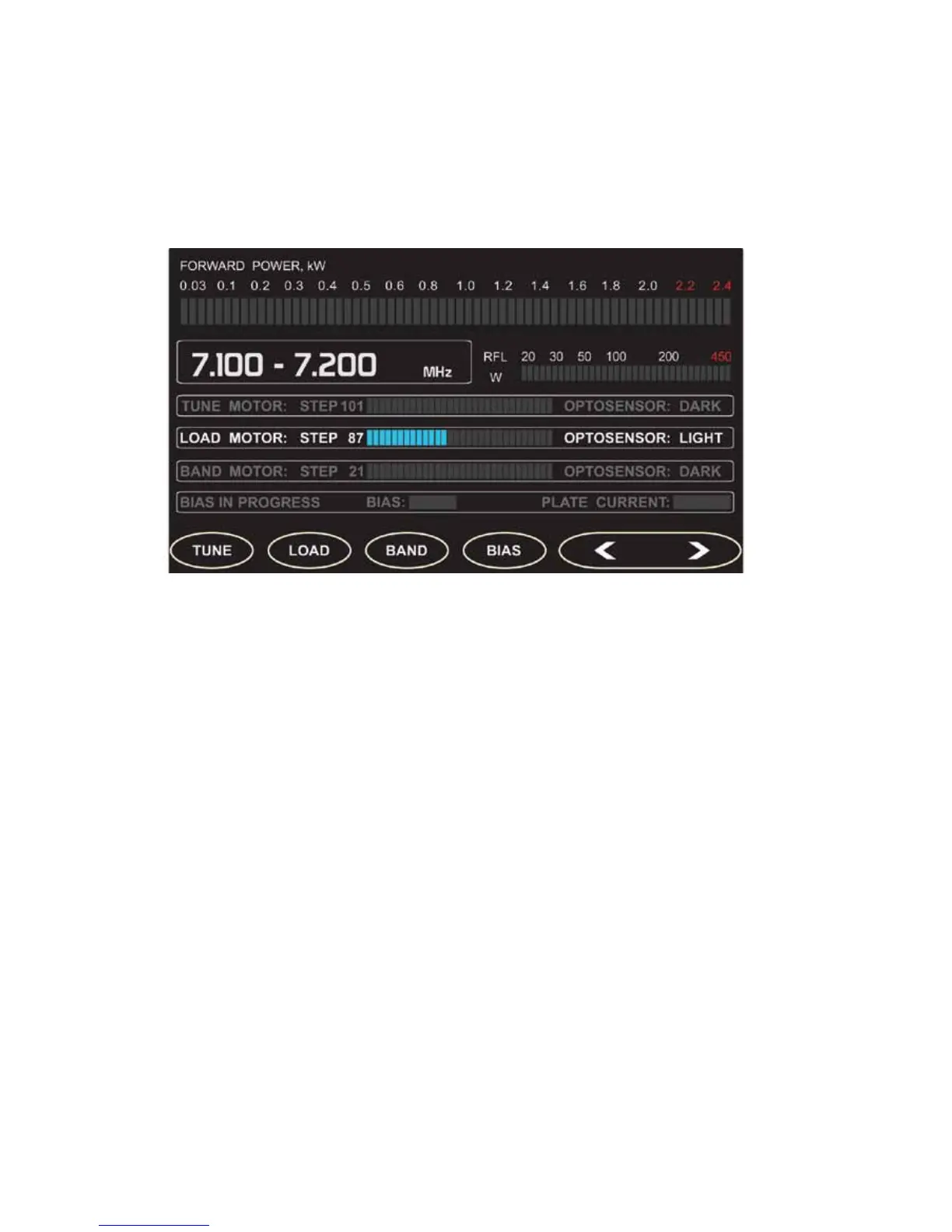
Fig.5-4 RCU display - SERVICE
When selecting TUNE, LOAD or BAND, the respective motor can be moved step by step CCW
or CW with the left and right arrow buttons. The positions of the motors are shown in a numerical
and in a graphical form. The status LIGHT or DARK of the respective optical sensors are also
displayed.
When the BIAS function is activated, it starts an automatic switching queue over three different
grid bias voltages. The voltages are shown along with the respective measured DC plate current.
This is used when the tube idling current adjustment is required.
If the amplier remains in the SERVICE sub-menu for more than 5 minutes without any
further RCU input, it will return automatically to the MAIN menu. For more information see the
TECHNICAL SUPPLEMENT.
5-4. CAT SETTINGS
Here you set the type of the transceiver connected by CAT to the amplier. Use the UP and DOWN
buttons to move the pointer and exit with SET/EXIT button. Pay attention to the communication
speed shown in the brackets next to each transceiver type. Set your transceiver serial port to
the same Baud rate (speed).
 Loading...


