39
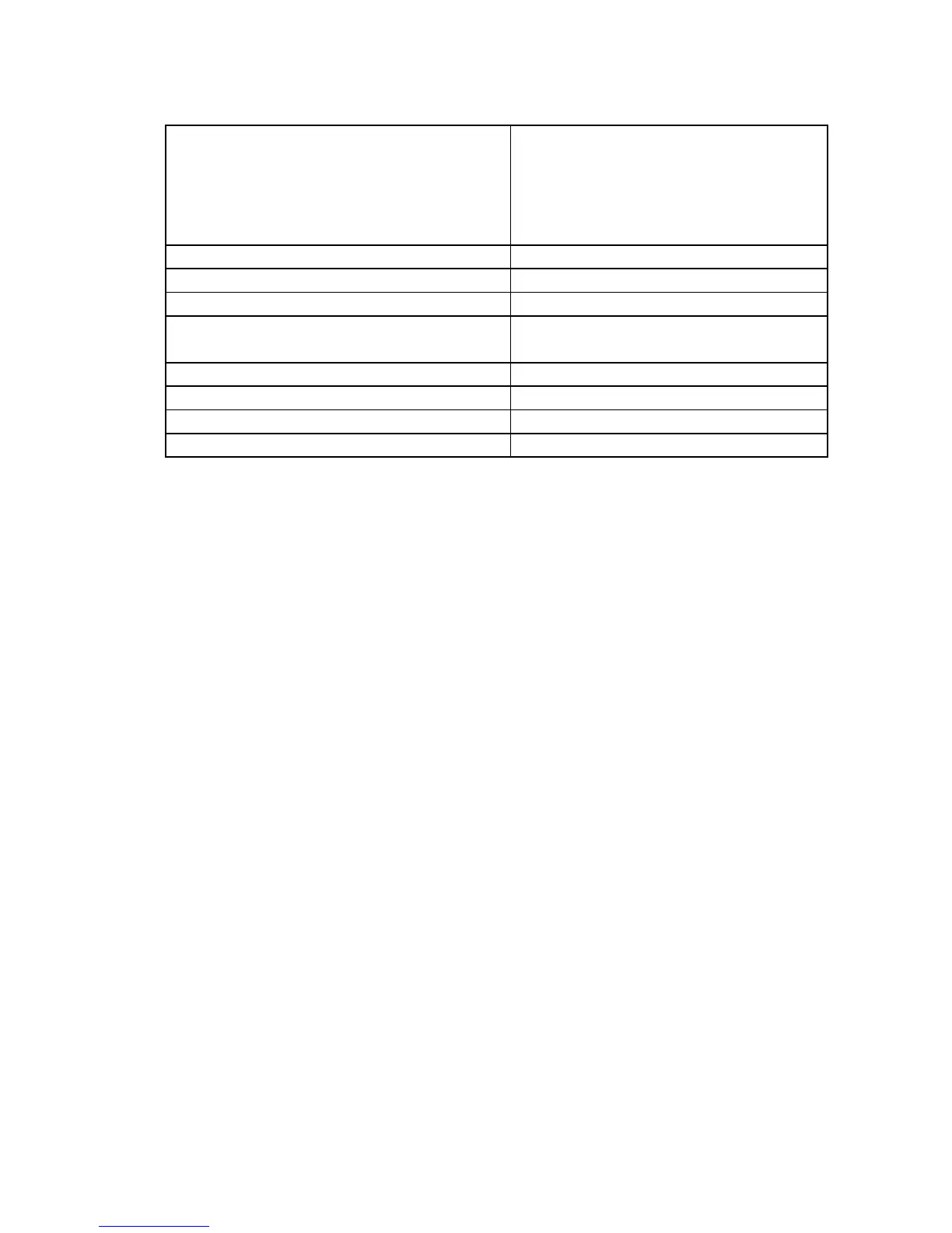
REFLECTED POWER TOO HIGH check antenna cable, selector, antenna and
grounding for loose contacts or worsened
insulation; trim the antenna for minimum
VSWR or use an antenna tuner; try another
antenna; check if REFLECTED POWER is
induced from another nearby transmitter.
REMOVE AND REDUCE DRIVE POWER RD&T*
RF PLATE =......V SHOULD BE ZERO OFF5*; CCC*
RF GRID =......W SHOULD BE ZERO OFF5*; CCC*
SCREEN VOLTAGE ON
BEFORE TIMEOUT OVER
OFF5*
TUNE CAPACITOR SYSTEM MALFUNCTION
OFF5*
+5V TOO HIGH (TOO LOW) CMV*
+/- 12V TOO HIGH (TOO LOW) CMV*
+24V /+48V TOO HIGH (TOO LOW) CMV*
* Abbreviations:
OFF5 - Turn the amplier off for 5 minutes and try again.
RD&T - Reduce drive power from transceiver; do AUTO TUNE - see S.4-2.
CMV - Check the mains voltage and verify that it matches the voltage selector
- see S.2-2 and table 2-1.
CCC - Check the control cable from the transceiver to KEY-IN input - see
S.2-4.
9. SPECIFICATIONS
9-1. Parameters
a) Frequency Coverage: All amateur bands 1.8-29.7MHz
b) Power Output: 1500W PEP or continuous carrier, no mode limit.
In continuous carrier modes (RTTY etc.) for transmissions longer than 15 minutes (up to several
hours depending on ambient temperature), the optional auxiliary fan must be mounted.
c) Intermodulation Distortion: Better than 35dB below rated PEP output.
d) Hum and noise: Better than 35dB below rated output.
e) Harmonics Output Suppression: Better than 50dB below rated output.
f) Input and Output Impedances:
• nominal value: 50 Ohm unbalanced, UHF (SO239) type connectors;
• input circuit: broadband, VSWR less than 1.3:1, 1.8-30MHz continuously (no tunings, no
switching);
• bypass path VSWR less than 1.1:1, 1.8-30MHz continuously;
 Loading...


