53
During the pauses, use a logic probe to make the following checks:
Toggle Mode Pulse Mode
U313-3 = LO U313-4 = HI
U312-3 = LO U313-14 = toggling
U316-9, 11, 14 = LO U315-13 = toggling
U316-12 = HI
After the pause, press "Continue" to generate the next trigger.
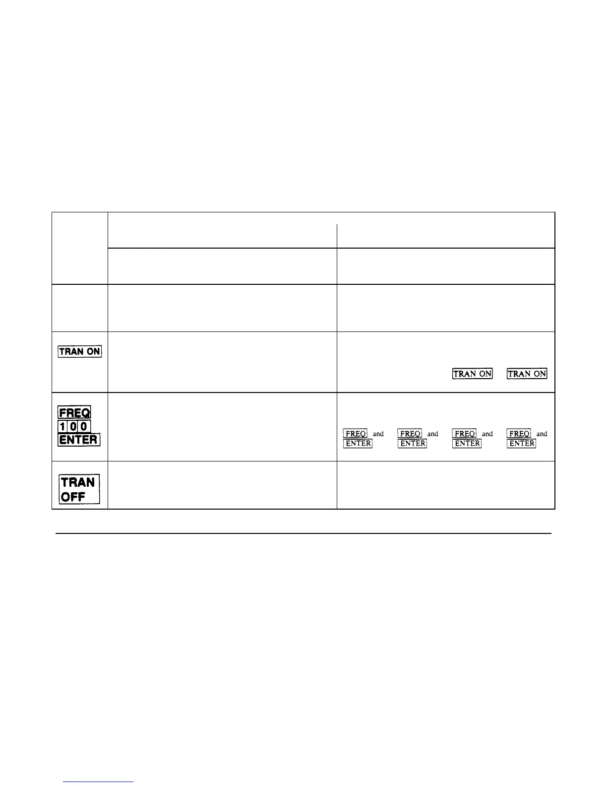
CHECKOUT TABLE
RESULT
FRONT
use scope use logic probe
PANEL
ACTION
TRANS_EN
signal
U316-
11,12
U313-
2,12,15
U312-
3
U313-
7
U313-
17
U313-5,8,
11,16,19
U316-
17,19
Turn on
unit
TTL Lo 11=LO
12=Hi
Negative
pulse
every
0.5ms
Negative
pulse
every
0.01ms
TTL Lo TTL Hi
Press
TTL Hi 1KHz sq.
wave
Negative
pulse
every
0.5ms
Negative
pulse
every 10
µs
TTL Hi TTL Lo Positive
pulse
when
pressed.
Negative
pulse
when
pressed.
Press
TTL Hi 100Hz sq.
wave
Negative
pulse
every 5ms
Negative
pulse
every
100
µs
Negative
pulse
when
pressed.
Positive
pulse
when
pressed.
Positive
pulse
when
pressed.
Negative
pulse
when
pressed.
Press
TTL Lo 11=LO
12=Hi
Negative
pulse
every 5ms
Negative
pulse
every
100
µs
TTL Lo TTL Hi
Trigger Circuit Troubleshooting (Figure 3-8)
The Electronic Load can receive an internal trigger (command via the GP-IB) or an external trigger signal (TRIG_IN via
connector TB201). Either trigger can be used in triggering a preset level (current, voltage or resistance value) or in
triggering a pulsed or toggles transient operation. Troubleshooting the trigger circuit consists of running programs that
generate trigger pulses and then making sure that the signal lines shown in Figure 3-8 toggle in the direction indicated. If a
signal line does not toggle where indicated, the gate or IC that generates that signal is probably defective.
The arrows on Figure 3-8 indicate the signal line activity when using a logic probe and running the programs. Connect
TP201-4 to TP301-2 (see Figure 3-2) before troubleshooting this circuit. This provides a common ground across isolation
for the logic probe.
The first program continuously toggles all signal lines labeled ON_TRIG when the program is run. Use the logic probe to
confirm this (see Figure 3-8).
 Loading...


