2 Making Measurements
22 U2000 Series Operating and Service Guide
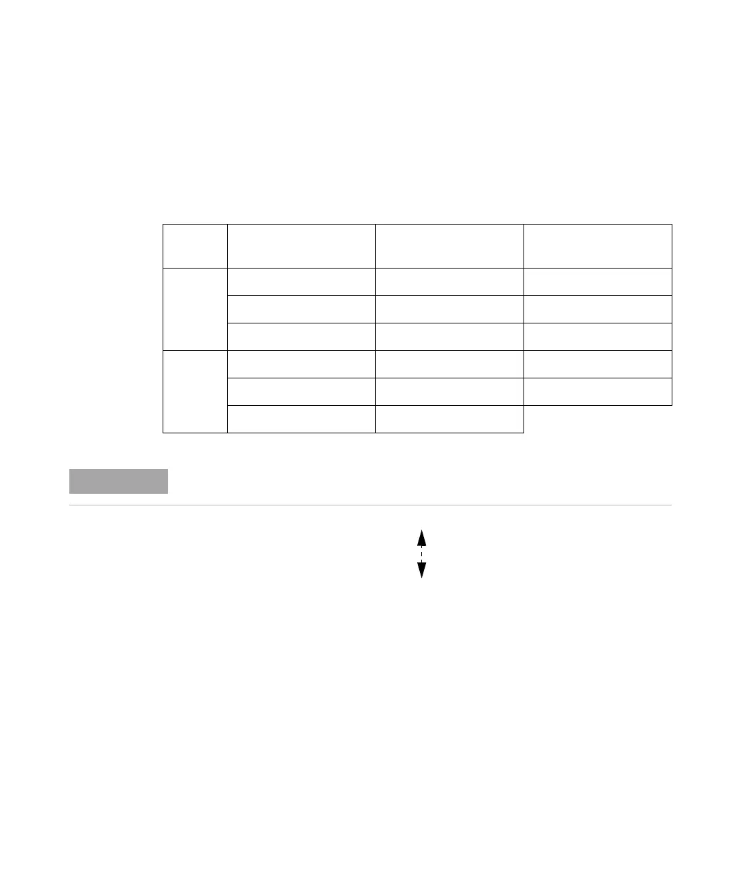
Power Sensor Configuration Settings
The calibration data of U2000 Series USB power sensors is automatically read
by referring to the specified range as shown in
Figure 2- 1 on the next page.
In Figure 2- 1, the dotted- line arrow indicates the internal range based on
the internal circuitry of the power sensor. The ranges will be automatically
selected in correspondence with the power level to best fit the operating
conditions and settings.
Power
Path
Power Level
(U2000/1/2/4A)
Power Level
(U2000/1/2H)
Power Level
(U2000/1B)
Low
Power
Path
–60 dBm to –35 dBm –50 dBm to –25 dBm –30 dBm to –5 dBm
–38 dBm to –15 dBm –28 dBm to –5 dBm +8 dBm to +15 dBm
–20 dBm to –9 dBm –10 dBm to –1 dBm +10 dBm to +21 dBm
High
Power
Path
–11 dBm to –5 dBm –1 dBm to +5 dBm +19 dBm to +25 dBm
–7 dBm to +15 dBm +3 dBm to +25 dBm +23 dBm to +44 dBm
+10 dBm to +20 dBm +20 dBm to +30 dBm
Averaging settings can also be manually configured.

 Loading...


