Making Measurements 2
U2000 Series Operating and Service Guide 25
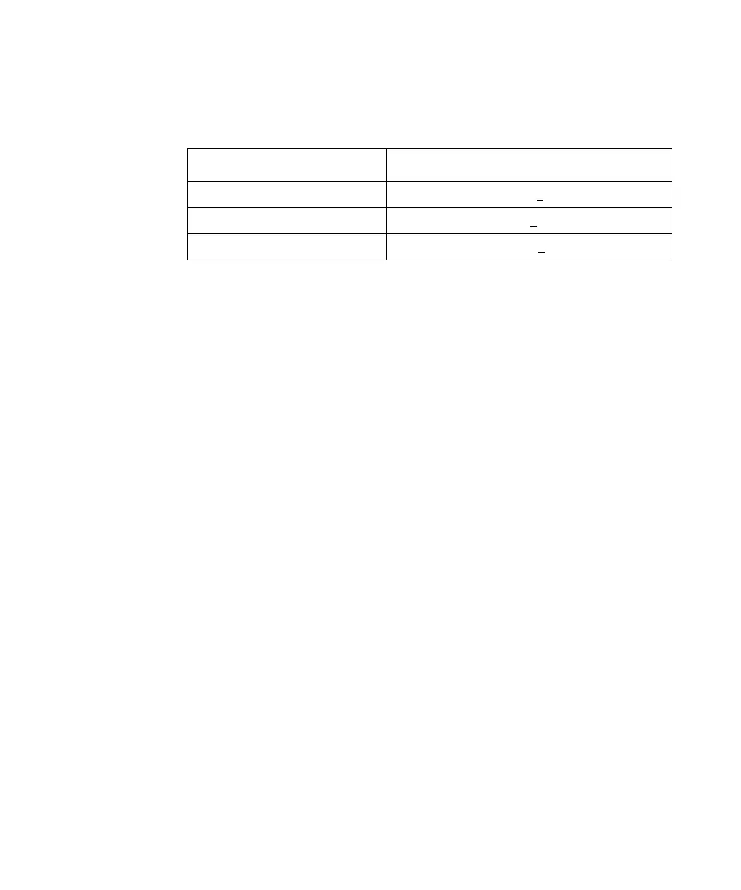
Tabl e 2- 2 Range Crossover Values
Measurement Considerations
While auto- ranging is a good starting point, it is not ideal for all
measurements. Signal conditions such as crest factor or duty cycle may cause
the power sensor to select a range which is not the optimum configuration for
your specific measurement needs. Signals with average power levels close to
the range switch point require you to consider your needs for measurement
accuracy and speed.
For example, a U2000/1/4A sensor, where the range switch point is –10 ± 1
dBm in a pulsed signal, should be configured as follows:
The calculated average power is –12 dBm.
Accuracy
The value of –12 dBm lies in the lower range of the U2000/1/4A sensor. In
auto- ranging mode (“AUTO”), the U2000/1/4A sensor determine the average
power level is below –10
dBm and select the low power path. However, the
peak amplitude of –6
dBm is beyond the specified square law response range
of the low power path diodes.The high power path (–10
dBm to +20 dBm)
should be used to ensure a more accurate measurement of this signal.
However, range holding in “UPPER” (the high power path), for a more accurate
measurement, results in a considerably increased number of filtering
processes.
Sensor Range Crossover Values
U2000A, U2001A, U2002A, U2004A –10 dBm + 1 dB
U2000H, U2001H, U2002H 0 dBm + 1 dB
U2000B, U2001B +20 dBm + 1 dB
Characteristic Value
Peak Amplitude –6 dBm
Duty Cycle 25%

 Loading...


