AHT Cooling Systems GmbH
on21.05.2018 21:36 Page 45
361929_0917_BA_SM_V4_06.09.2017_U_enUS_CD.docx
resistance. By default, the controllers are delivered
with the bus address “1” (corresponds with a “stand-
alone” device).
For the identification of several devices in a bus
system, the bus addresses must be assigned
beginning with 1. Bus addresses must not be assigned
more than once. Then we recommend entering the
addresses according to the actual wiring sequence. In
doing so, max. 247 addresses are possible.
Procedure for assigning the bus addresses:
1.) Press the [STANDBY RESET] button for at least
3 seconds.
“---” is shown on the display.
Now the cooling function is switched off.
2.) Press the [+/-] button 3 times successively after
that.
“Adr” is shown on the display alternately with
the current bus address, e.g. “1”.
3.) Assign the next highest bus address (individual
step):
Press the [+/-] button briefly.
Quick run through the bus addresses:
Press the [+/-] button for longer
4.) Accept new entry:
Wait for 5 seconds.
“---” is shown on the display.
NOTE
Property damage when assigning the bus
addresses by switching off the cooling function.
►After assigning the bus addresses, the cooling
function must be switched back on again (see →
Point 5).
5.) Switch the cooling function back on.
Press the [STANDBY RESET] button for a
minimum of 3 sec.
The current temperature is shown on the display.
6.) Repeat points 1 to 5 on each device and set a
free bus address.
Semi-automatic defrosting
1.) Start the semi-automatic defrosting:
Press the [MAN DEFROST] button briefly.
“dEF” is shown on the display.
Defrosting duration: up to 99 min. (device-specific).
24-hour defrosting block:
If “---” is shown briefly on the display and then the
temperature, the 24 hour defrosting block is active.
2.) End the semi-automatic defrosting:
The device automatically reverts to normal mode. The
current temperature is shown on the display again.
Alarm display and acknowledgment
Alarm display:
The fault code flashes alternately on the display with
the temperature. The red point illuminates on the
display at the same time (see Fig. 3 No. 4).
Depending on the fault, an acoustic signal can also
be issued by a built-in buzzer (device-specific).
Alarm acknowledgment:
Fault code and acoustic alarm (device-specific):
Press the [STANDBY RESET] button briefly.
The current temperature and the red point are shown
on the display. The red point (see Fig. 3 No. 4)
illuminates until the fault has been rectified.
Calling up the fault code in-between:
Press the [STANDBY RESET] button briefly.
The fault code is shown on the display for
approx. 5 seconds. Then the current
temperature is shown on the display again.
List of fault codes:
Excessive temperature alarm
Excessive temperature at F4
Insufficient temperature alarm
Excessive temperature electronics
Compressor fault due to E75
Voltage outside tolerance
Frequency outside tolerance
No communication with the display
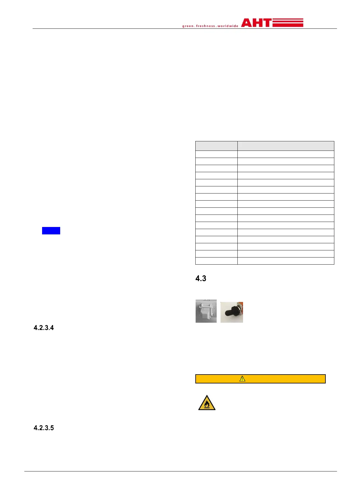
Internal switch device lighting
An internal switch (device-specific) is available to
switch the device lighting on/off.
Fig. 4: Example for device lighting internal switch
5 Transport and storage
Check the device for transport damage after delivery.
Contact the maintenance service in case of damage
(see → Chapter 10.5).
For devices of type R-290: Damage to
refrigerant circuit. The refrigerant can
escape and create an explosive gas/air
mixture. Risk of fire.
►Do not expose the device during
storage and transport to temperatures
higher than 70°C (158°F).
►Ensure good ventilation.
►Observe the safety and warning
information for devices with flammable
refrigerants (see → Chapter 1.6.2.1).
 Loading...