Malfunctions with Indications 2-5
Fault Status Indicators
The Bulletin 1395 contains various Fault Status Indicators which can be
used to monitor the faults that occur in the drive. These are available for use
with the Bulletin 1300 Programming Terminal (DHT/DMT), the PLC/Node
adapter, the PLC/Data Highway +, the Multi Communication Adapter and
through the use of discrete I/O devices.
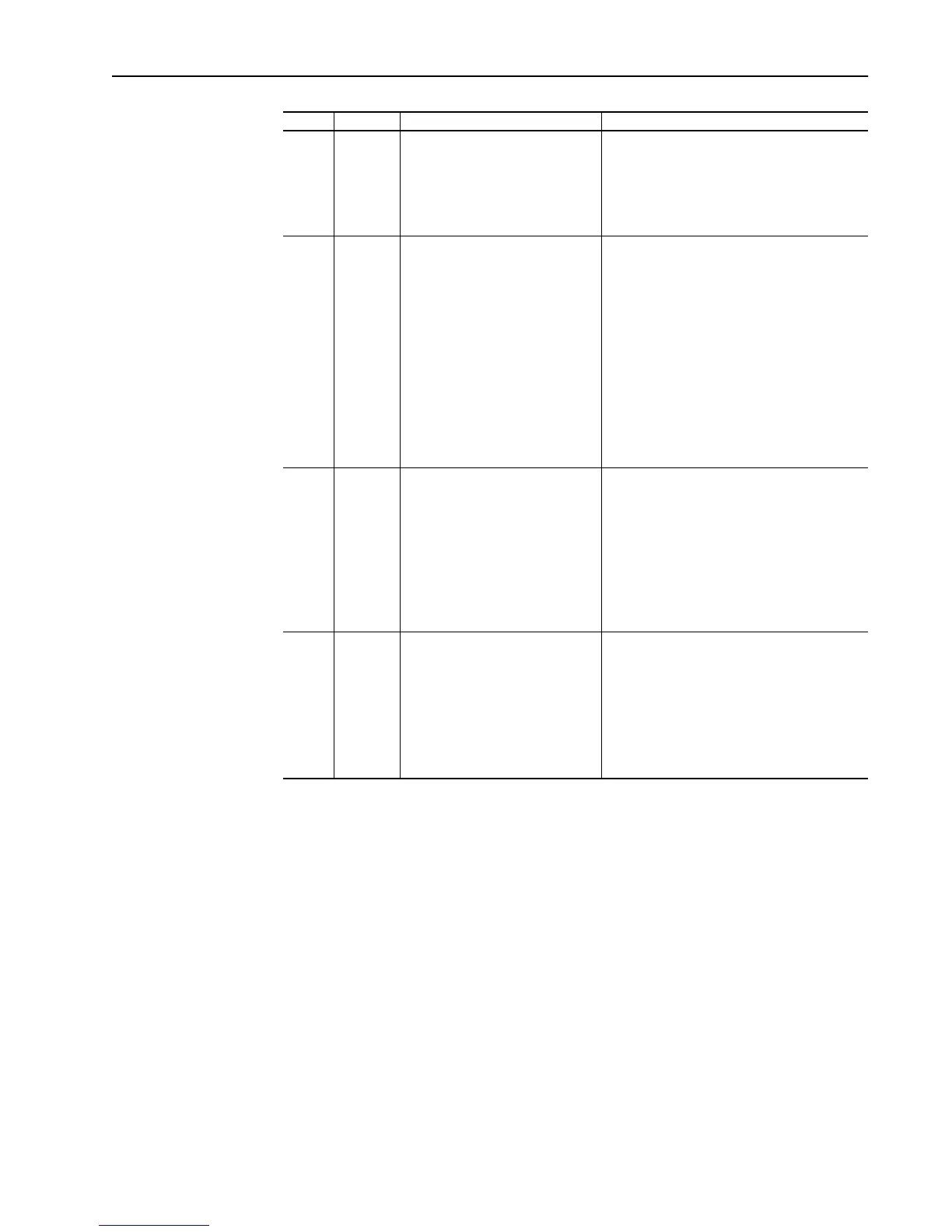
VP-16 Thermal
Overload
Pending
This Warning fault occurs when the
armature current exceeds the Motor
Overload Pending Level.
Parameter 720 “Ovrld Pend Level”. It is used to
indicate that the present armature current output
exceeds a predetermined level and continued
operation at this level may cause damage to the
motor and/or process. This warning fault can be
disabled. Refer to Parameter 632.
VP-17 Thermal
Overload
Tripped
This selectable fault occurs when
armature current output over time
has exceeded the selected motor
overload coefficients.
Parameter 629 “Mtr Overload Sel”. This
parameter is used to select the coefficients for
the motor thermal overload function.
0. Overload function disabled
1. 60 seconds to trip at 150% armature current
for externally cooled motors.
2. 60 seconds to trip at 200% armature current
for externally cooled motors.
3. 60 seconds to trip at 150% armature current
for self cooled motors.
4. 60 seconds to trip at 200% armature current
for self cooled motors.
VP-18 Motor
Stalled
This selectable fault occurs when
the armature output is at current
limit and velocity is within the zero
speed tolerance for the time delay
specified.
Parameter 727 “Stall Delay”. This parameter
indicates the time that the armature current must
remain at current limit with the motor velocity
within the zero speed tolerance before the above
fault is indicated. Programmable range: 0-100
seconds.
See also parameters 663 “Fwd Brdg Cur Lim”,
664 “Rev Brdg Cur Lim”, and 710 “Zero Speed
Tol”.
VP-20 AC Voltage This selectable fault occurs when
the incoming AC line voltage
exceeds +15% or –20% of rated AC
line voltage for the time delay
specified.
Parameter 617 “Rated AC Line”. This parameter
indicates the incoming AC line voltage and is
used as a basis for the above comparison and
resulting fault. Programmable range: 150-460V.
Parameter 728 “AC Line Tol Dly”. This parameter
indicates the time the AC Line must remain out
of tolerance before the above fault is indicated.
Programmable range: 0-1.0 secs.
No. Name Description Associated Parameter(s)
Aotewell Ltd industry-mall.net

 Loading...


