Malfunctions Not Indicated by a Fault 3-15
Armature Current Control
Armature current control is performed in the Current processor. Most of the
malfunctions that occur produce fault responses that indicate the problem.
In some cases improper tuning will cause nuisance faults and abnormal
operation to occur. If the armature control parameters are improperly
calibrated, malfunctions will occur and possible damage to the drive may
occur. Most malfunctions described here will deal with the symptoms the
drive will exhibit when the parameters are misadjusted.
Following is a list of malfunctions, symptoms, and possible solutions.
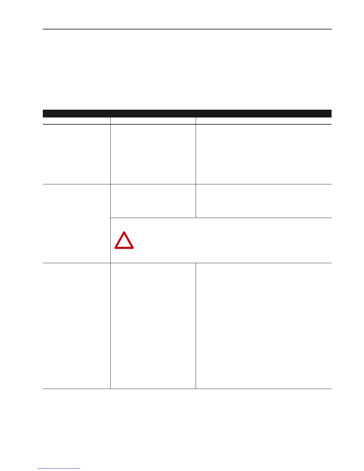
Armature Current Control Malfunctions
Malfunction Symptom Solution
Armature current output is well
below rated or well above the
rated level. This results in
decreased or increased
available torque. The velocity
control up to and including the
commanded torque has been
checked and is functioning
properly.
The armature current reference is below
the level called for by Torque Command.
When Parameter 110 “Torque
Command” is 100%, Parameter 111
“Arm Current Ref” should reflect the
motor’s rated armature current. The
torque command should remain
proportional to the armature current
reference from zero to base speed.
• The ratio of torque command to armature current reference is
wrong. This ratio is calculated based on Parameters 611
“Motor Arm FLA” and 615 “Rated Arm Brdg 1”. Parameter 611
should reflect the nameplate full load armature current rating of
the motor. Parameter 615 should reflect current rating of the
drive as listed on the product label. If either of these
parameters is incorrectly entered, the armature current output
will be incorrect.
Measured armature current to
the motor does not equal the
commanded armature current.
The armature current measured by the
clamp on ammeter is not equal to the
current reflected in parameter 112 “Arm
Current Fdbk”.
• Verify parameter 615 reflects the bridge current rating of the
drive as listed in the Start-Up chapter of the Installation
Manual. If incorrect, the armature current output scaling will be
incorrect and the level of the current to the motor will be
inaccurate.
A step in torque command
causes the drive to trip on an
overcurrent trip.
A step in torque command results in a
excessive pulse of armature current,
faulting the drive.
• The current loop may be improperly tuned. If the gains are too
high the step command will cause the current regulator to over
react and produce too much current. Tune the drive to the
proper current loop gain using the Autotune procedure.
• Reduce the value of Parameter 668 “dI/dT Limit”. This
parameter limits the rate of change allowed for the armature
current reference. By reducing this value, the control will
increase the armature current reference at a slower rate when
given a step torque command.
• Verify that all six pulses are present in the armature current
waveform. To monitor the armature current waveform place a
scope probe on test point TP5 on the Main Control Board.
Reference the scope to TP57 AGND. If one or more are
missing, a malfunction in the power structure has occurred,
refer to Magnetics/Power Structure section of this chapter for
further details on correcting armature bridge malfunctions.
• Check the motor commutator for signs of arcing and excessive,
or rough, brush wear. Consult a motor rebuilder.
!
ATTENTION: If a Feedback Board is ever replaced due to a component malfunction, the
scaling resistors mounted in TB2 and TB3 will be transferred to the new board prior to
installation. If TB2 and TB3 resistors are omitted or improperly installed, the current
scaling will be incorrect and damage to the drive may occur.!
Aotewell Ltd industry-mall.net

 Loading...


