3-22 Malfunctions Not Indicated by a Fault
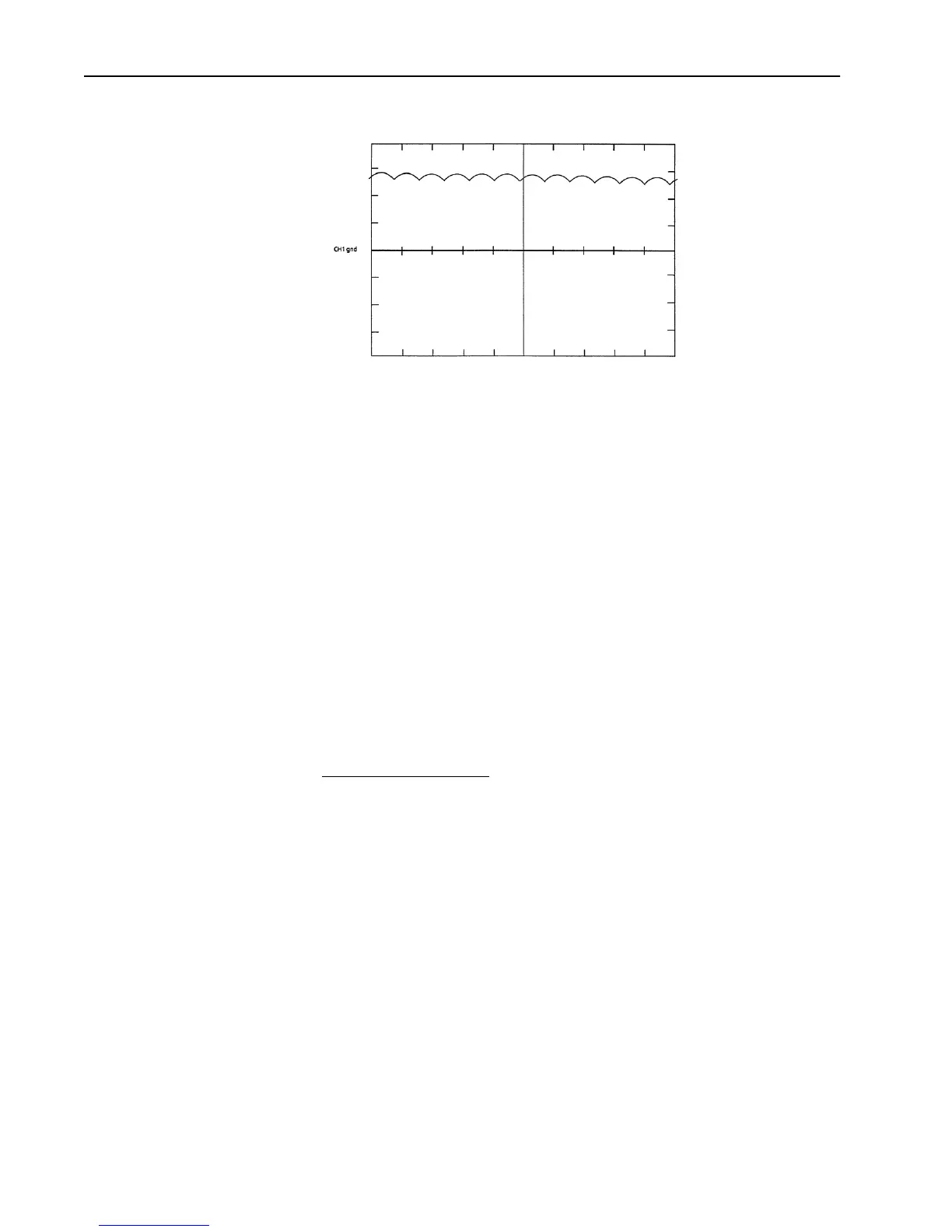
Figure 3.12 Field Current Feedback (TP25) - Continuous Current
Magnetics/Power Structure
The 1395 drive contains a power structure that has an armature and field
supply. The armature supply consists of a three–phase, full wave rectified,
dual bridge, capable of four quadrant output. The field supply consists of
single phase, full wave rectified bridge. Also associated with the power
structure are the low voltage logic power supply and the 24V unregulated
power supply, contactor control circuits, and incoming line protection
devices. The procedures below are designed to identify damaged
components by standard troubleshooting techniques. Note that the
troubleshooting information in this section is divided into two sections. All
Series A troubleshooting information precedes Series B troubleshooting.
Series A
1-100 HP, 230V AC
2-200 HP, 460V AC
Armature SCR’s (Series A)
The 1395 (1-100 HP, 230V AC & 2-200 HP, 460V AC) armature supply
consists of six dual pack SCR modules mounted on the main heatsink. A
malfunction of any of these devices will show itself in either an overcurrent
related fault, blown or tripped incoming protection devices, or erratic motor
operation. The following procedure can be used if an armature bridge
component malfunction is suspected.
1. Disconnect and lock–out ALL incoming voltage sources. Verify that the
three–phase high voltage is removed from the incoming protection
devices, either F1 – F3 or the main circuit breaker CB1. Also verify that
the 115V logic supply and contactor power is removed from TB2–3,4,
and 5. If an external field supply is used, verify that it is also removed by
checking TB1–1 and 5.
2. Check the Anode to Cathode junction of each SCR module. With a DVM
on the 1 Megohm scale, measure the resistance across the SCR modules
as follows: (Note: Lead orientation is not critical).
Aotewell Ltd industry-mall.net

 Loading...


