38 Rockwell Automation Publication CNET-IN005A-EN-P - May 2011
Appendix A 1756 ControlNet Status Indicators
Interpret the Network Channel Status Indicators
The network channel status indicators appear in one of these states:
• Steady—The indicator is on continuously in the defined state.
• Alternating—The two indicators alternate between the two defined states
at the same time (applies to both indicators viewed together). The two
indicators are always in opposite states, out of phase.
• Flashing—The indicator alternates between the two defined states (applies
to each indicator viewed independent of the other). If both indicators
flash, they must flash together, in phase.
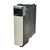
1756-CN2/B, 1756-CN2R/B,
and 1756-CN2RXT
ControlNet Communication
Modules
This section provides the following information about status indicators:
• To understand the OK status indicator and display messages, refer to
Table 1 on page 39
.
• For information about viewing the network channel status indicators
together, refer to Table 2 on page 42
.
• For information about viewing the network channel status indicators
individually, refer to Tab le 3 on pa g e 42
.
When you connect the module to a ControlNet network using only the
NAP, the channel A and channel B indicators are meaningless.

 Loading...


