16 Rockwell Automation Publication 1769-UM021G-EN-P - October 2015
Chapter 1 Install the CompactLogix 5370 L1 Controller
Before You Begin
The CompactLogix™ 5370 L1, series B, controller redesign occurred to provide
an option to use one external power supply for system power and field side power.
There are differences between the CompactLogix 5370 L1, series A and B,
controllers, which are detailed throughout the sections of this manual.
Consider the following before installing a CompactLogix 5370 L1 controller:
• The control system includes the controller, an embedded power supply,
and embedded I/O points.
• The embedded power supply for the series A L16ER, L18ER or L18ERM
controller is a 24V DC nominal, non-isolated power supply with an input
range of 10…28.8V DC. You wire the embedded power supply via a
removable connector.
• The embedded power supply for the series B L16ER, L18ER, L18ERM
and series A L19ER controller is a 24V DC nominal, isolated
power supply with an input range of 10…28.8V DC. You wire the
embedded power supply via a removable connector.
ATTENTION: If this equipment is used in a manner not specified by the
manufacturer, the protection provided by the equipment can be impaired.
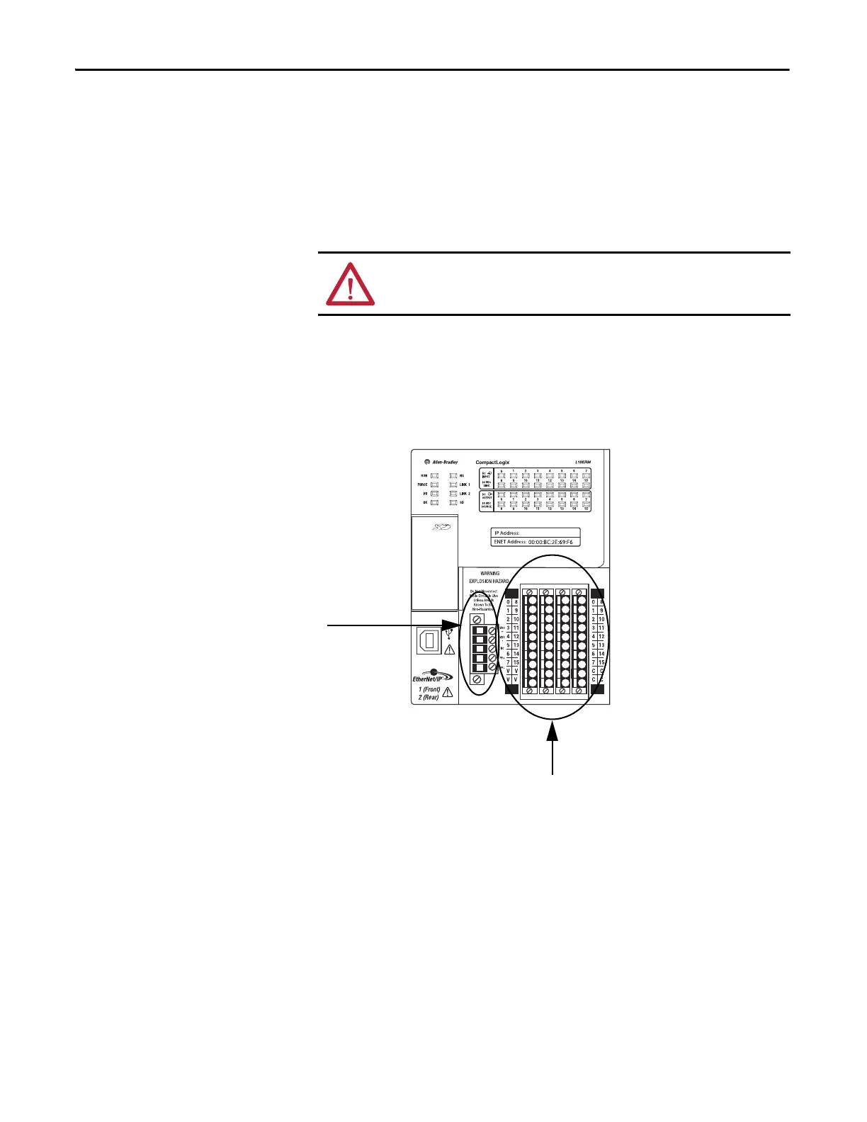
Removable Connector for
Embedded Power Supply
Embedded I/O Module
 Loading...

