72 Rockwell Automation Publication 22C-UM001J-EN-E - January 2017
Chapter 3 Programming and Parameters
T072 [Analog In 1 Loss] Related Parameter(s): T055
, T060, T065, T069, T070, T071, A152
Stop drive before changing this parameter.
Selects drive action when an input signal loss is detected. Signal loss is defined as an analog signal less than 1V or 2mA. The signal loss event ends and normal operation resumes
when the input signal level is greater than or equal to 1.5V or 3mA. If using a 0-10V analog input, set T070 [Analog In 1 Lo] to a minimum of 20% (i.e. 2 volts).
The drive will fault on an F29 Analog Input Loss
when the analog signal is lost if this parameter is used for the PID feedback, and this parameter and A152 [PID Ref Sel] are both set
to an option other than 0 “Disabled”.
Options 0 “Disabled” (Default)
1 “Fault (F29)” F29 Analog Input Loss
2 “Stop” Uses P037 [Stop Mode]
3 “Zero Ref” Drive runs at zero speed reference.
4 “Min Freq Ref” Drive runs at minimum frequency.
5 “Max Freq Ref” Drive runs at maximum frequency.
6 “Preset Freq0” Drive runs at A143 [Preset Freq 0].
7 “Hold Last” (with FRN 6.xx and
later)
Drive uses last frequency command from analog input prior to signal loss, or last PID reference prior to signal loss when used as a
PID reference.
T073 [Analog In 2 Sel] Related Parameter(s): P038, T055, T065, T074, T075, T076, A152
Sets the analog input signal mode (0-20mA, 4-20mA, 0-10V, -10 to +10V). This parameter must match DIP Switch AI2 setting on the control board.
.
Values Default: 2
Min/Max: 0/7
Display: 1
T073 Option Setting Input Range DIP Switch AI1 Setting
0 Current Mode 0-20 mA 20 mA
1 Current Mode 4-20 mA 20 mA
2 Voltage Mode - Unipolar 0-10V 10V
3
(1)
(1) Setting 3 is only available on [Analog In 2 Sel]. Input 2 is isolated and supports a bi-polar input, so that setting 3
determines if the voltage input is enabled for bipolar control. If bipolar is selected, P034 [Minimum Freq] and
T074 [Analog In 2 Lo] are ignored. If input 2 is set up for current control, Bipolar mode is not possible. If the
analog input is inverted ([Analog In 2 Lo] > [Analog In 2 Hi]), Bipolar mode is disabled and this input uses
unipolar control only (negative values are treated like zero).
Voltage Mode - Bipolar -10 to +10V 10V
4 Current Mode (Square Root) 0-20 mA 20 mA
5 Current Mode (Square Root) 4-20 mA 20 mA
6 Voltage Mode - Unipolar (Square Root) 0-10V 10V
7 Voltage Mode - Bipolar (Square Root) -10 to +10V 10V
T074 [Analog In 2 Lo] Related Parameter(s): P034, P038, T072, T073, T075, T076, A152, A153
Stop drive before changing this parameter.
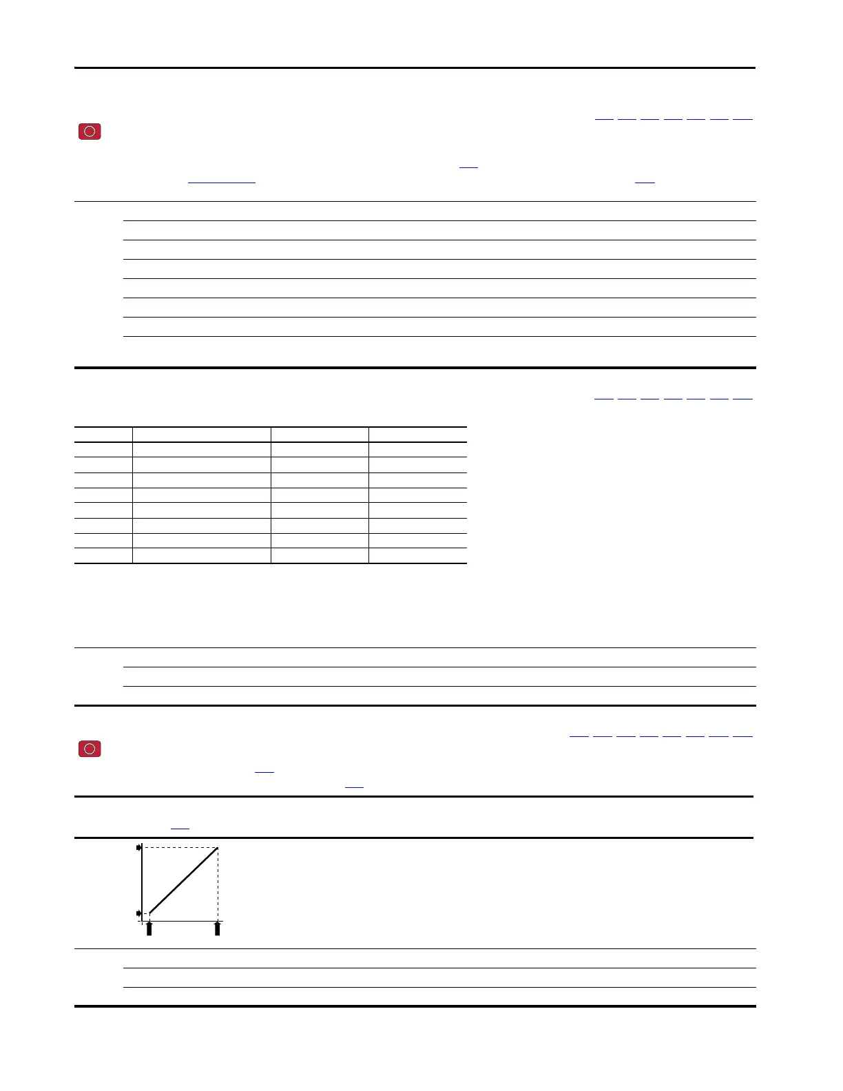
Sets the analog input level that corresponds to P034 [Minimum Freq].
Analog inversion can be accomplished by setting this value larger than T075 [Analog In 2 Hi].
Values Default: 0.0%
Min/Max: 0.0/100.0%
Display: 0.1%
IMPORTANT
If analog inversion is implemented the drive will go to maximum frequency in the event the analog input is lost. It is strongly recommended to activate
T072 [Analog In 1 Loss] to protect from this potential occurrence.
0
P035 [Maximum Freq]
P034 [Minimum Freq]
T074 [Analog In 2 Lo] T075 [Analog In 2 Hi]
0
Speed Reference
 Loading...