6 DeviceNet ArmorBlock™ Network Powered 16-input Module
Publication 1732D-IN007B-EN-E - November 2011
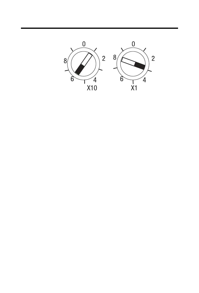
Node Address Default Setting
The rotary switches are read periodically. If the switches have been changed since the last
time they were read and no longer match the online address, a minor fault occurs, which is
indicated by the module indicator flashing red.
Settings of 64…99 cause the module to use the last valid node address stored internally. For
example, if the last setting internally was 40 and the setting is changed to 68, when you
power up, the address defaults back to 40.
The module is equipped with AutoBaud detect. AutoBaud lets the module read the
settings already in use on your DeviceNet network and automatically adjusts to
those settings.
Mount the Module
Use the two sets of mounting holes to mount the module directly to a panel or machine.
Mounting holes accommodate #6 (M3) pan-head screws. The torque specification is
0.64 Nm (6 lb-in.).
Refer to the mounting dimensions diagram to help you mount the module.
43968
This example shows
the default node
address set at 63.
 Loading...