8 DeviceNet ArmorBlock™ Network Powered 16-input Module
Publication 1732D-IN007B-EN-E - November 2011
Connect the Cordsets
The ArmorBlock DeviceNet family has 5-pin micro-style connectors. We provide caps to
cover the unused connectors on your module. Connect the quick-disconnect cordsets you
selected for your module to the appropriate ports.
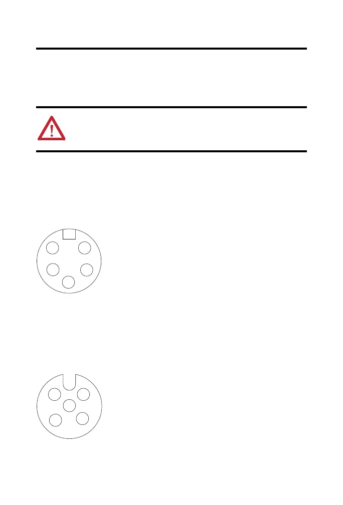
Network Connector
Refer to the pinout diagram for the network connector.
Mini-style Input Male Connector
I/O Connectors
Refer to the pinout diagram for the I/O connector.
Micro-style 5-pin Female Input Connector
ATTENTION: To comply with the CE Low Voltage Directive (LVD), all connected
I/O must be powered from a source compliant with the following: Safety Extra
Low Voltage (SELV) or Protected Extra Low Voltage (PELV).
1
5
3
4
2
(View into connector)
Pin 1 Drain
Pin 2 V+
Pin 3 V-
Pin 4 CAN_H
Pin 5 CAN_L
43901
1
5
3
4
2
(View into connector)
Pin 1 Sensor source voltage
Pin 2 Input B
Pin 3 Return
Pin 4 Input A
Pin 5 PE
41452
 Loading...