60 Rockwell Automation Publication 5069-UM003A-EN-P - May 2018
Chapter 4 Configure Compact 5000 I/O Serial Module
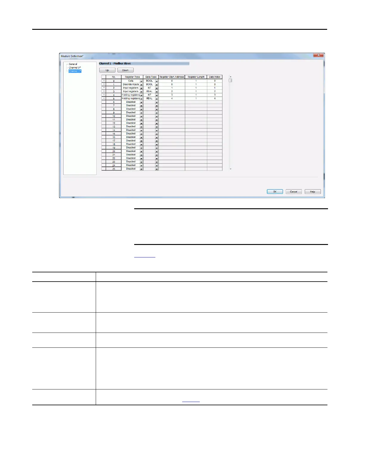
Figure 10 - Modbus Slave Module Definition Parameters
Tabl e 14 shows definitions of the Modbus Slave configurable parameters.
IMPORTANT On the module definition screen, you will see two options at the top for
moving the commands up and down. If either of these buttons are used,
make sure the user program is adjusted to reflect the new location of the
command or the program will show and error.
Table 14 - Modbus Slave Module Definition Parameters
Parameter Definition
Register Type • Disabled (default)
•Coils
•Discrete Inputs
• Input Registers
• Holding Registers
Data Type • BOOL
•INT
•REAL
Register Start Address • 0…65535
(default = 0)
Register Length • Dependent on Data Type
–BOOL: 1…128
(default =1)
– INT: 1…100
(default = 1)
– REAL: 1…50
(default = 1)
Data Index Location of data in the output or input tags depending on the register type defined.
For more information, see the following section on Data Index
.
 Loading...


