Publication 1761-UM006A-EN-P - February 2001
Installation and Wiring 2-3
Mounting
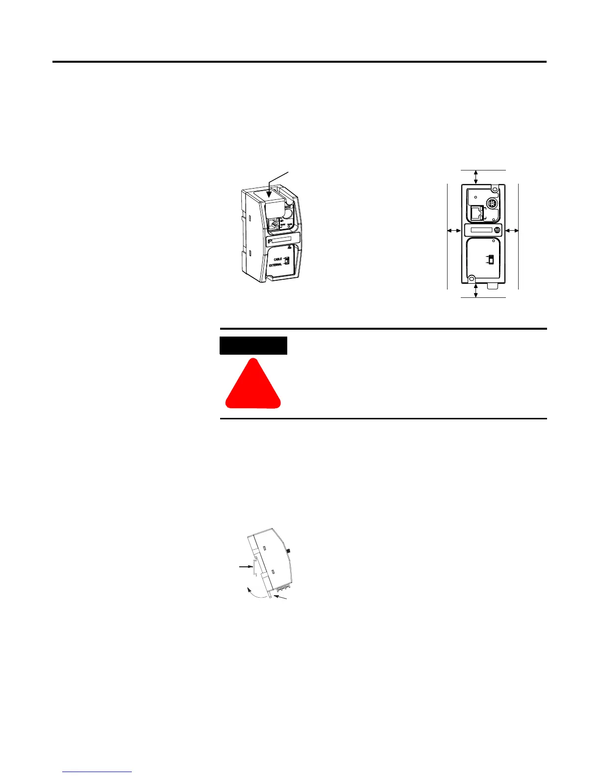
The 1761-NET-ENI must be mounted in the vertical position, as
shown. Horizontal mounting is not recommended due to thermal
considerations. Allow 50 mm (2 in.) of space on all sides for adequate
ventilation. See page A-1 for operating temperature specification.
DIN Rail Mounting
Installation
ATTENTION
!
Do not remove the protective debris strip until after
all the equipment in the panel is mounted and wiring
is complete. Once wiring is complete, remove
protective debris strip. Failure to remove strip before
operating can cause overheating.
protective debris strip
ETHERNET
FAULT
RS232
NET
TX/RX
TX/RX
PWR
CABLE
EXTERNAL
IP
top
bottom
side side
DIN
Rail
Latch
1. Mount your DIN rail.
2. Snap the DIN rail latch into the closed
position.
3. Hook the top slot over the DIN rail.
4. While pressing the unit against the rail,
snap the unit into position.
 Loading...