Publication 1761-UM006A-EN-P - February 2001
Installation and Wiring 2-5
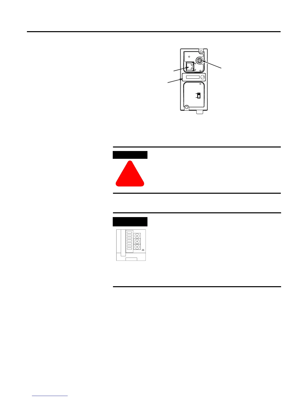
ENI Port Identification
External Power Supply
Wiring
ETHERNET
FAULT
RS232
NET
TX/RX
TX/RX
PWR
CABLE
EXTERNAL
IP
Write-on area for
Ethernet IP address
RS-232 Mini-DIN (ENI Port 2)
Ethernet Port (ENI Port 1)
WARNING
!
EXPLOSION HAZARD - In Class I Division 2
applications, an external, Class 2 power supply must
be used. The DC Power Source selector switch on
the ENI must be set to EXTERNAL before connecting
the power supply to the ENI.
IMPORTANT
• In non-hazardous locations, external power is not
required. Some devices (such as a MicroLogix
controller) provide power to the ENI via a cable
connected to ENI port 2. Be sure to set the DC
power source selector switch to match your
particular configuration, CABLE or EXTERNAL.
• Always connect the CHS GND (chassis ground)
terminal to the nearest earth ground. This
connection must be made whether or not an
external 24V dc supply is used.
VDC
24
DC
NEUT
CHS
GND
Bottom View
 Loading...